|

Tools and Materials
|
OVERVIEW:
The tachometer needs power, ground and a signal. I attempted to pull the signal from the speedometer pin #3 as in the instructions. This worked on 2004 and 2005 models and may still work on other 2006 models, but I was not able to get a signal that would work from this pin. Instead I wired power and ground from the speedo connector for convience, but I got the tach signal from the ECM connector (pin #3 coincidentally) in the electrical caddy.
PARTS:
SERVICE MANUAL (not optional!)
qty1 H-D mini tach (kit came with wires, gasket, etc.)
qty1 flush head screw for holding tach in cup (my tach kit included one because it came with a cup, some kits do not include one)
qty1 Alloy Art SM-3 chrome stem nut tach mount
qty1 Crimp on terminal socket for ECM connector (72076-00)
qty2 Clamp on wire taps
some dielectric grease and other misc. stuff
TOOLS:
Phillips screwdriver (for seat removal)
Straight screwdriver
5/16" wrench or socket (deep?) for tach post nuts
Allen wrench of hex sockets (1/4", 3/16", 5/32")
Wire strippers
Diagonal cutters
Zip ties (wire ties)
DISCLAIMER:
Basically, perform this at your own risk. Many people are perfectly comfortable doing things like this to a vehicle under warranty and many others are not. If you are not, DO NOT ATTEMPT. I have NO idea what risk you run of voiding your warranty although it seems unlikely this would cause a problem unless you damage something in the process. This setup may or may not be suitable for your bike, but it is working for me.
|
|
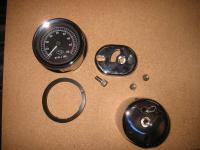
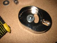
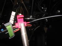
Here you can see the key parts of the tach mount as well as the tach itself and the gasket.
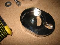
In case the pictures throughout don't give a clear idea of how this mount works . . . The mount consists of the cup and the base. The base is screwed on top of the stem nut. The tach is installed into the cup and held in place by a screw from the bottom.
The base is elongated and allows the cup to be mounted eccentric to the stem post. The offset is enough that the cup is screwed onto the base from the bottom. There is enough room behind the top triple tree to access this screw.
|
The key parts
|
|
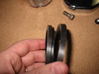
Cut the gasket in half
|
As per the Alloy Art instructions, you need to cut the gasket in two.
The picture probably explains best where the cut needs to be made, but you basically need to cut the largest diameter section off the back of the gasket and discard it.
|
|
Slide the gasket onto the tachometer. The edge with the larger diameter will go under the tach face rim.
Make sure you line up the 2 rounded notches on the gasket with the grooves in the tach housing.
|
Put gasket in place on the tachometer
|
|
Make connections
|
I bought my mini tach as part of a dealer close out. This was part of a kit for softail customs (with a bracket, wires, sheathing, etc.)
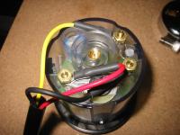
There are three binding posts marked:
+ G S
My kit had a 3 wire rig with each wire in a sheath and the bundle in a larger sheath. One end of each wire has a ring connector that works perfectly on these binding posts.
Hook up as follow:
Red wire to + for power
Black wire to G for ground
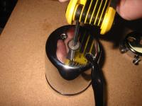
Yellow wire to S for a signal
The posts has 5/16" nuts on them. I used a deep socket on a driver although a wrench should do fine.
HINDSIGHT: I should have coated these with dielectric grease. I will disassemble and do this as soon as possible since this housing is not completely sealed. Water can enter through the same hole these wires exit the housing although this cup has a drain hole at the lowest point . . . good design.
|
|
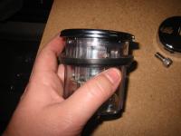
Run the wires out the hole in the bottom of the cup and install the tach into the cup. Use the provided flush head screw to hold the tach in place (5/32" allen). I used Blue Loctite.
The wire outlet in the cup will exit towards the front of the bike. Of course, you need to line up the 12 o'clock on the tach with that wire outlet so that when you mount the cup, the tach will be oriented correctly.
|
Install tach in mounting cup
|
|
Remove stem nut cover
|
The stem nut cover just screws on. To unscrew it, just turn it CCW.
|
|
|
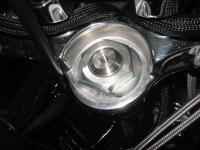
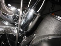
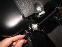
Here is a picture of the stem post and nut. You can see the threaded hole in the post. The cover screwed into this and the tach mount will use this same threaded hole.
|
The stem post and nut
|
|
Problem!!!
|
I'm not sure this picture will show it clearly, but the flush head screw has a deep head. The head extends above the inside surface of the base in this picture.
This is important because when you thread this in place, the screw will obviously stop when you run out of threads. Because this head is thicker than the material you are mounting . . even when fully tightened, the base will be loose.
|
|
I just grabbed a washer and the problem is solved. This washer is thick enough so that only threads are visible. This should work fine.
HINDSIGHT: I will probably get a stainless washer with some kind of "bite" to it. The base wants to move around when tightening.
|
Solution!!!
|
|
Install the base
|
With that washer in place, I screwed the base in place over the stem nut making sure to line it up straight. Blue Loctite.
|
|
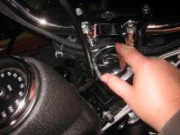
I hope this picture is clear enough, but you need to use the 1/4" allen bolt to mount the cup to the base. The polished aluminum part you see is the back of the top triple tree. The screw goes up through the bottom of the base and into the bottom of the cup. Blue Loctite.
HINDSIGHT: As I mentioned with that washer, I think I should put something thin in between the cup and the base. These slick pieces move like crazy when you attempt to tighten that bolt. It is tricky to keep the base AND the cup in alignment. I am wondering if a thin rubber "washer" might work here, another vibration damper as well perhaps?
|
Mount cup onto base
|
|

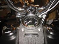
Pic of mounted tach
|
Pic of mounted tach
|
|
|
Pic of mounted tach
|
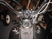
Pic of mounted tach
|
|
Profile pic of mounted tach
|
Profile pic of mounted tach
|
|
I lost the pciture of me removing the seat, but I'm sure you can handle it ;-)
You need to use a 3/16" allen wrench or socket to remove the bolts holding the dash panel in place.
|
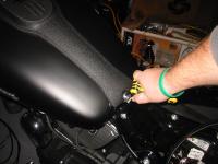
Remove seat and dash panel
|
|
Upper dash bolts too
|
The upper dash bolts are 3/16" also.
|
|
A little out of order here, I should have shown where I have the wires routed up to now. I don't have a picture that shows it. The wires exit the bottom of the cup towards the front of the bike.
I routed these wires down through the wire chase in the top triple tree along with the wires from the hand controls. I then pulled the wires along the left side of the neck to the dash area. Make sure you leave plenty of slack so that you can turn the handle bars from lock to lock without stressing these wires.
(picture shows the clutch cable is between my wires and the neck. I actually did the opposite.)
|
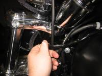
Route the wires
|
|
Snip zip ties
|
On the inside of the dash panel, there are probably a couple of zip ties holding the wiring harnesses in place. Cut any of them necessary so you will be able to disconnect the dash entirely from the bike.
|
|
|
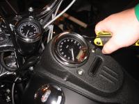
The rubber booted odometer reset switch cover simply screws onto the switch. To remove it from the dash panel, unscrew it and remove the switch.
|
Remove the odometer reset switch
|
|
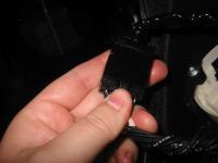
Disconnect indicator lights
|
Press the release tab on the indicator light connector and unplug it.
|
|
|
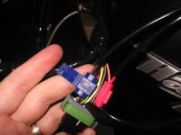
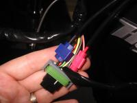
The speedo connector has two locking tabs on the sides. Release those with a screwdriver and unplug this connector. At this point your dash panel should be completely free of the bike.
|
Unplug the speedometer connector
|
|
Begin routing wires
|
Strip the outer sheathing back to roughly this point.
REMINDER: You'll need to make sure you have plenty of slack available for this cable without having to snip zip ties, etc. If this set of wires does not have enough slack, you will not be able to get the tach back out of the housing without a lot of headaches. The tach needs to be able to come completely out of the mounting cup in order for you to have access to the electrical connections.
|
|
|
Slide the individual wire sheaths for power and ground so that they go inside the bundle sheath by an inch or two.
|
Move individual sheaths for power and ground
|
|
Route the signal wire
|
I used an adhesive backed mounting pad to zip tie the signal wire in the lower part of the dash area. This makes it easier to keep that single wire running down the center of the tank.
HINDSIGHT: I probably had enough sheathing for that signal wire to slide it all the way back under the bundle sheath with the others. If possible, wait until you finish routing this wire to decide. The more protection, the better.
|
|
The mini tach instructions tell you to wire power from an unused fuse block and ground to the chassis ground. I had no fun trying to figure out the easiest way to get the wire terminated behind the fuse block so I cheated.
The Dynas that come with a tach share power and ground with the speedo, so I suspect the wiring and the fuse are stout enough to handle the load of a tach on my FXDBI as well.
This works fine, but be aware of this. You may want to wire to the fuse block and the chassis ground as instructed.
|
I took power for the tach right off the speedometer connector
|
|
Tap tach power into the power wire on speedo plug
|
The red wire from the tachometer needs to be spliced into the orange and white wire on the speedometer plug (pin #1). Drawing 12VDC from this wire ensures the tach will always be on and lit when the speedo is on and lit.
I am not sure the correct name for the clamp on wire taps. There are two channels inside these things. One goes all the way through, put the wire you are tapping into through there. The other channel does not go all the way through, put the tach red wire in that channel and clamp the metal "guillotine" down.
This will penetrate the insulation and make contact with both wires. Then flip the protective cover over and snap it locked.
|
|
|
Repeat the procedure for the tach ground wire. I cannot remember which pin this was, but it is the only black wire in that speedometer connector.
|
Tap tach ground wire into the speedo ground
|
|
Power wires finished
|
Your tach should now have power. Plug this connector back into the speedometer temporarily. Put the key in the ignition and turn it on. Make sure the speedometer and tachometer power up and light up.
HINDSIGHT: Now is probably a good time to make sure you are happy with the lighting colors. You may not be able to get a perfect match with the speedometer, but it is easiest to tinker with that before assembling everything. The bulbs use silicon boots to color the light. I put a yellow boot on the tach light and it still doesn't match. The speedo uses LED lighting and is not serviceable. I'll have to research the options for getting the tach color right.
|
|
I am missing a few pictures here, but reconnect the connectors inside the dash panel and zip tie things as needed. Put the dash panel in place being careful not to squash that fuel tank vent line.
Also, you'll be routing the yellow tach signal wire right down the middle of the dash panel to the seat area. You'll need to be careful that the wire is not squashed when tightening the dash in place as well.
|
Reinstall the dash panel
|
|
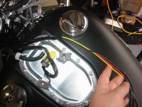
Route the signal wire
|
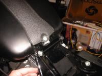
In this picture and the previous one, I hope it is clear that I bring the wire from under the dash panel on the left side of the dash panel mounting bolt.
There is room just inside that left tank mounting tab to bring the wire down through a hole. This is important so you keep the wire clear of the mounting tab on the front of the seat. You'll slide that seat tab under this bolt in the center, so that wire needs to be off to the side to avoid threat of being cut or damaged.
|
|
|
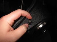
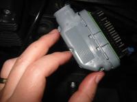
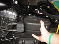
The electrical caddy cover is held in place by two posts that press fit into a rubber sleeves. Literally just pull it straight out (two hands is better).
|

Remove electrical caddy cover
|
|
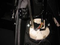
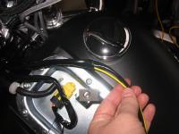
Route the signal wire
|
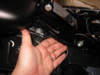
I tuck the wire up under the lip of the seat pan and bring it to the area of the electrical caddy. Right about the end of my ring finger is the back edge of the electrical caddy and the precise spot we'll bring that wire.
|
|
|
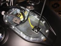
Route the cable through this hole in the electrical caddy from behind.
|
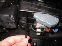
Pull the wire through the opening in the caddy
|
|
Prepare ECM connector
|
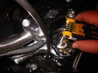
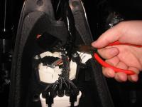
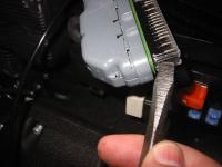
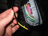
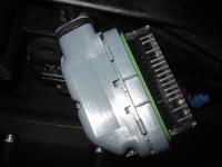
On the under side of the ECM connector is a release tab. Press the release tab and pull the connector free from its socket.
There is a clear plastic cover surrounding all of the small sockets on the connector. On each end, there is a release tab. As in the picture, press this tab with a screwdriver and release the cover (remember to release BOTH sides).
|
|
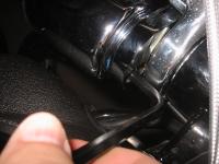
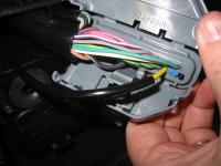
At the neck of the connector (where the wire bundles enter) you need to snip the zip tie that goes around the neck and wire bundle. In this picture, the zip tie was already snipped.
There are three locking tabs that hold the cover closed. Release all three of these using a small screwdriver to pry them if necessary.
|
Open up the ECM connector cover
|
|
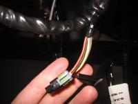
Prepare the tach signal wire
|
Cut the signal wire to length (see the next picture to see exactly where it needs to go). Strip the sheathing back and strip the insulation as well.
The service manual is invaluable for this type of thing. There are explicit instructions about how much wire to expose for each type of connector.
|
|
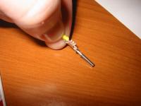
Crimp the "Terminal Socket" appropriate for this connector, H-D 72076-00 onto the tach signal wire. The proper tool no doubt makes this a lot easier, but if you are careful, you can get a good crimp. You need to crimp these in such a way to maintain a round shape, don't just squash the crap out of it or else you'll never get the crimped area into that small hole in the ECM connector.
The set of tabs at the end of the crimp are are designed to crimp the insulator. The rest are designed to crimp the wire itself to form the connection.
|
Crimp the socket connector onto tach signal wire
|
|
Install tach signal wire into ECM connector
|
Pin #3 is unused (and unlabeled in the wiring diagrams) but there is a suitable tach signal here. There is probably a blue plug in socket #3, remove it with a small screwdriver.
This wire is actually probably one size too big for this connector, though I was able to get the insulation to fit inside the connector socket.
Slide the metal connector and wire into the ECM connector until the socket clicks in place. Check it from the front of the connector and make sure that the socket for pin #3 looks like it is in the same position as all the others.
|
|
gather together the bundle of wires and close the connector cover. Make sure the wires are not being pinched and make sure the 3 locking tabs engage.
Put a new zip tie around the neck of the connector and the entire bundle of wires. Zip it tight and snip off the extra.
Install the clear connector cover and make sure the locking tabs on both ends engage.
|
Reassemble ECM connector
|
|
Finish up!
|
Plug the ECM connector back in. Crank up your bike to make sure everything is working OK. You should get a legit tach reading near 1k if it is cold.
If everything worked OK, you should put the electrical caddy cover back in place and reinstall your seat. . . you're all done.
|
|
I will take a better picture without the clutter of my garage as a backdrop as soon as it stops raining down here in FL. It seems like we haven't seen the sun in weeks.
While I am griping . . . is that diamondback clutch cable I paid for over 5 weeks ago ever going to come off backorder?
|
Done!
|
|