Warning: Undefined array key "visitDate" in /home2/sap/public_html/header.php on line 6
Garage Door Opener - Tutorial View

Warning: Undefined array key "session_logged_in" in /home2/sap/public_html/header.php on line 612
home | shopping | contact | projects | login|join
     Garage Door Opener       
Search Projects:
 
Share Thumbnails Slideshow Tutorial

Garage Door Opener
Submitted By: kpreese
Date Created: 04-21-2006
Description: I've been using a keypad remote to open my garage door for my bike. I've been concerned about this on those rare late night situations because I can coast past all the houses in my neighborhood, but I have to park the bike, dismount, enter the code to open the door, remount the bike and rev it to get the bike moving again and into the garage.

Ideally, when approaching the house, I could have the door opening and then I should be able to coast all the way up the driveway and into the garage without making much noise at all. I ran across the HD opener kit which I discuss below. I wasn't able to use that, but I decided I could come up with a good solution.

The HD garage door opener kit is pretty slick. You flash your brights and that triggers the transmitter which is wired to the bike and doesn't need batteries.

The downsides are:
1. Retail price is $126.95
2. While it uses a revolving code system like my Genie, it still means using two separate receivers and that's twice the risk of accidental openings or someone gaining access.
3. Flashing the brights as I approach the house could annoy the neighbors (I doubt it though provided the headlight was pointed straight down the street) and I'd have to wait if an oncoming car was passing.
4. My particular opener does NOT have an extra set of terminals for an external switch. It indicates in the manual that only ONE wall switch be connected to these terminals. I suspect that the HD unit could be made to work, but if I take the manual at face value, then it will not work.

But this solution seems to work quite well.
Related Projects: H-D 2006 FXDBI Street Bob
    Lighting updates (run/turn/brake controller, LED blinkers and tail light)
    Tachometer
    License Mount
    Fat Mini-Apes
    Horn Cover
    (Garage Door Opener)
    New Exhaust


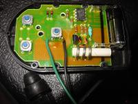
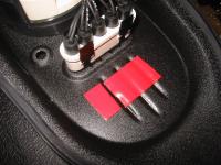
Guts of the Genie remote
This is a 3 button Genie remote. The newer ones use 1.5V AAA batteries, but the remotes that I have in the cars use 12V batteries. So I bought a replacement for one of my cars, so I can use one of these 12V beauties for the bike.

You can see the three switches in a triangle pattern on the left side in this picture. I've already soldered some 22 gauge wire onto the primary switch as you can see.

These wires are connected to one of HD's odometer reset switches, which you can also see at the bottom of the picture.

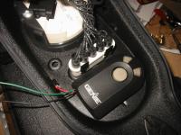
I soldered some 22 gauge wires to the battery contacts.
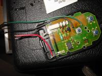
Power wires soldered in place


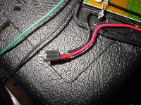
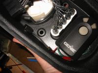
Installed Deans connector to power wires
I used a Deans connector (RC battery packs) so the dash panel can be fully disconnected from the bike's wiring harness.

I soldered some power leads to the other half of the Deans connector.
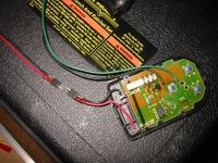
Power leads prepared


Double sided tape inside dash panel
I use a foam, double sided tape to mount the remote below the inidicator lights in the dash panel.

Here is a shot of the remote in place.
Remote mounted


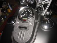
Switch installed on dash
I installed the odometer reset switch on the right side of the dash opposite the real odometer reset switch. WOW, this was difficult to get positioned correctly. Everything on this dash is rounded and so trying to make precise measurements is tough with no clear reference points.

I think I got it reasonably close. Even in pictures, if the camera isn't dead-center it looks off. So this is one of those things that you're better off not obsessing over. Move one way and the left one appears higher, move another way and the right one appears higher . . .GOOD ENOUGH!!!!

This picture shows the switch installed from the inside.

Here is the switch, viewed from the outside.
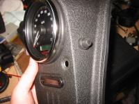
Switch installation from the outside


All done!
I forgot to take pictures of splicing the power wires. I tapped into the ignition power (orange/white) and the ground (black) on the connector for the speedometer. This way the opener will work anytime the bike's key is turned on, but WON'T work otherwise. I don't leave the bike parked outside, but you never know.

I think it turned out well. It looks OEM and will never need batteries. I haven't tested the range yet, but regardless, it was still worth doing.

All projects on Shareaproject.com are user-submitted and should be used for reference information only. The projects are not intended to be complete "How-To" articles. Use the information contained in these projects at your own risk. Projects are not checked for completion, accuracy, or safety and therefore cannot be guaranteed in any way.
Outdoor Blog