|
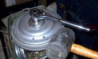
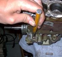
Remove Flywheel Nut
|
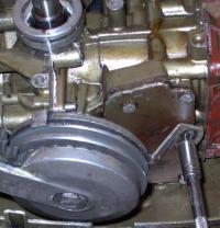
Here's how I remove the flywheel nut from the outboard. Leave the spark plugs in, set up a socket wrench and strike it with a rubber mallet. The compression will hold the flywheel from rotating.
|
|
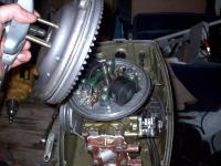
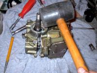
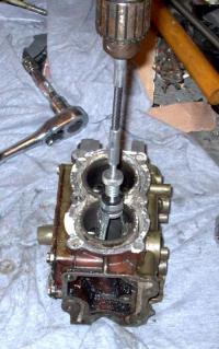
Here I'm using a common automotive harmonic balancer puller and three 1/4"-20tpi Grade 8 bolts 4" long to pull the flywheel. This is really overkill on the 4hp but I use the puller for other outboards, and it's less violent than the hammer method. For the hammer method, see Tom Travis' www.outboard-boat-motor-repairs.com website.
|

Pull the flywheel
|
|
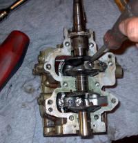
Remove the flywheel
|
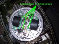
This is what you find underneath.
|
|
|
Pull off the points cam and set it aside. Then completely loosen the 4 phillips screws.
|
Loosen the magneto plate
|
|
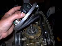
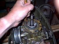
And lift it off
|
It should lift right off. Next remove the brass ring and the aluminium ring beneath it.
|
|
|
This pull start is a pain in the neck to deal with. If it's working fine, your best bet is to avoid messing with it altogether. Put a clamp on it to hold the pulley to the starter's body and remove the small bolt from the exhaust plate and the large bolt in the centre of the starter. The large bolt holds all the components of the starter together.
|
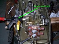
Remove the pull start
|
|
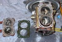
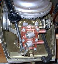
Remove the fuel pump
|
Simply remove the two slot screws near the centre of the fuel pump. There's no need to remove the top and bottom screws, which actually hold the pump together. You may re-use the fat fuel pump gasket.
|
|
|
Simply use a 7/16" crescent wrench to remove the two carb nuts and pull the carb forward so the carb studs will clear when you pull the engine.
|
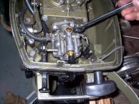
Remove the carburetor
|
|
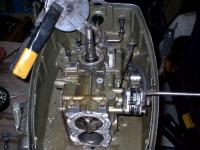
Remove the lower cowling/engine assembly
|
These four bolts must be removed to take the "head" off the outboard. It would be much simpler if you remove the lower first. Check the lower unit subproject for details.
|
|
|
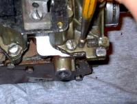
With the engine/lower cowling assembly off you can proceed to remove the engine. First, the long exhaust tuner will have to come off. There's some screws underneath it you'll have to get to. At this point you're faced with removing some nasty 1/4" slot screws that are (doubtless) rusted into place.
|
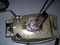
Remove the exhaust tuner and engine
|
|
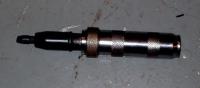
Stop cursing OMC's engineers
|
And get yourself an impact screwdriver. This can be had fairly cheaply from discount tool stores or ebay. The way it works is that you strike it with a heavy hammer while turning the screw. The downward blow is transformed into a rotary motion, which helps break the corrosion's grip. If this doesn't work by itself, you'll need to heat the area around the screws with (at least) a MAPP torch.
|
|
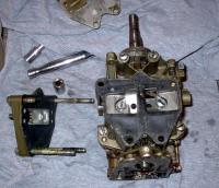
The intake manifold comes off easily enough. Just remove the four screws and tap it off.
You should probably pull the head as well at this point if you haven't already. Since this was the very first thing I did, I don't have a picture. Simply remove the 6 bolts, set the aside, and tap the head off. Actually, there's a handy boss for you to pry against at the top of the head & block.
|
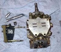
Ok, now that you've got the engine off, start pulling it apart
|
|
Remove the reed cage.
|
If it hasn't yet, pop it off as well. There's nothing holding it on.
|
|
|
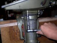
These are tapered to exactly align the front half of the crankcase/block with the back half. They must be driven out from the small side, or you'll crack the block. A small punch and hammer works well for this. Next, remove the screws that hold the crankcase together. There are 6 total, 4 on the periphery and the two behind the reeds.
|
Remove the locating pins
|
|
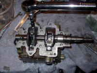
Separate the crank halves
|
These are still held together by the crankcase halves' sealant. Grab the block and tap the top of the crank with a mallet to drive it out.
|
|
First, keep note of which cap belongs to which rod and the orientation of each cap. I mark my caps T(op) or B(ottom) with a Sharpie, and then draw a line between the cap and the rod.
Next, you need to remove the caps. First, bend back the locking tangs on each rod cap screw with a screwdriver, then simply unscrew the connecting rod screw and set them and the caps aside.
|
Remove the connecting rod caps.
|
|
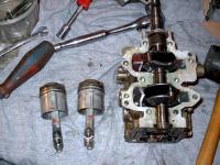
Remove the pistons
|
These just pop right out. Keep track of which one is the top & bottom piston and rod assembly. You'll want to put them back where you found them.
If you look close, you can see that the top piston has overheated and expanded to the point where it scuffed. Probably the skirt is collapsed a bit too. The bottom piston has water damage and a score. I do plan to replace them someday with oversized ones, just not now.
|
|
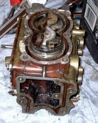
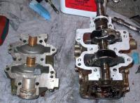
I've drawn this one out because it's such a common problem on both 3 and 4hp Johnson/Evinrude engines from the 50s, 60s, and 70s. This is the complete cooling water circuit. If you click on the image, you'll see that there are actually two parallel circuits. One that bypasses most of the block and primarily cools the exhaust, and a much more constricted passage around the cylinders themselves.
All too frequently, the small passage out of the cylinder jacket area gets blocked causing the engine to run far too hot. Make sure at this stage that all these passages are clear.
The bypass passage over the top of the block has a tendency to clog as well, since it's at the top. If the cooling system is weak, the top of the block gets the hottest. In a salt water environment, calcium carbonate will precipitate out of the seawater especially quickly when it's heated above about 60�C. So this passage frequently ends up clogged with calcium carbonate on neglected outboards.
|
Disassembly complete. Check out your cooling passages.
|
|
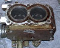
Honing the bores
|
Here I'm using a common automotive brake hone to remove the glaze on the cylinder walls. On these little 1.56" bores, it's practically the only honing tool that will fit. Use as much pressure as you can get out of the tool, and work it with a variable speed drill. The idea is to produce a 60� crosshatch. That means turning the drill pretty slowly and moving it in and out pretty rapidly.
The grooves you put into the cylinder wall will help hold oil and therefore increase compression. You want to remove as little actual material as possible. If you're too aggressive with the hone, you'll wear the bore out of round or taper, which will ruin the engine.
|
|
After you're done deglazing, you must remove every trace of grit from the hone. This means careful scrubbing with dish detergent and hot water. I use a stiff bristled tooth brush. Clean and clean again.
Immediately after cleaning, wipe the cylinder walls with a TC-W3 outboard oil soaked rag. If you do not, they will start rusting in no time.
For some reason this picture didn't come out very well. The crosshatch is in fact a lot nicer than it appears.
|
Clean the block
|
|
Install the pistons
|
Put the pistons back in the right way around. The ramped side of the piston must face the exhaust port. Check and double check this. Also, if you're reusing the pistons make sure you've got the top piston in the top bore.
The rings will need to be compressed so you can fit them back in. No need for a special tool for this - just use your fingers.
|
|
Lubricate the top main bearing with TC-W3 outboard oil and set it on the top journal. Set the crankshaft into the block and align the connecting rods.
Next, install the caps on their rods, orienting them the same way as you found them. Place the locking washers on the screws, and then screw on the caps until they're just snug. Then torque them up using an inch/lb reading torque wrench to 35 inch/lbs first, then 50 inch/lbs, and finally 65 inch/lbs. Do not attempt to use a ft/lb reading wrench since they are woefully inaccurate at these lower settings.
Bend over the locking tabs on the washers with a punch so the screws cannot possibly back off.
|
Install the crankshaft
|
|
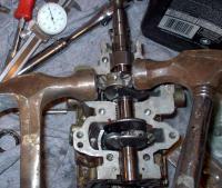
Align the caps
|
To align the caps, use two hammers. One will act like an anvil. Hold one hammer against the side of the rod's big end bearing and tap the other side with the other hammer. Then tap the centre of the cap from above. Finally tap the other side of the rod's big end bearing like the first.
|
|
Clean the crankcase faces completely so they're free of oil and old gasket compound, including the area around the top main seal. Use acetone or chlorinated brake cleaner. Coat all the faces with a thin layer of the appropriate sealer, being careful not to get any on the crank's journals. Coat the outside of the top main seal with sealant and place it into it's final position.
While waiting for the sealant to set, lubricate the connecting rod bearings and piston skirts with TC-W3. Be careful not to get any on the sealant. I use a oil dispensing needle for this.
A note on sealants: The correct sealant to use is "Sealer 1000", sometimes known as "Marpox 1000", and is now distributed under the "Boat Armour" brand name. This is no longer available from BRP, so the suggested replacement is "3m #847 Scotch Grip Rubber and Gasket Adhesive", PN 776964. I am using Permatex Motoseal #1 Grey #38401, which is a very similar product. It requires a 5 minute setup period before final assembly.
Do not use any form of RTV silicone as it is intolerant to gasoline and will keep the crankcase halves apart slightly. The dark brown type Permatex appears not to be resistant to oxygenated fuels, and is too weak to be used by itself anyway. The above sealants I mention are all flange sealants, which will squeeze out any excess.
|
Seal the crankcase
|
|
Assemble the crankcase
|
Screw in all the main bolts and periphery bolts, but just snug them. Then install the two tapered pins by driving them tight with a punch to align the crankcase halves.
Torque the main bolts in three rounds. Start with the centre bolts, then the uppers, and finally the lowers. Do the first round at 35 inch/lbs, second at 50 inch/lbs, and the final round at 70 inch lbs on all the bolts. Then tighten the periphery bolts. If you wish to torque these, they get 70 inch/lbs as well but there's no need to tighten them in three rounds.
Drip a little 2-stroke oil into the crankcase to lubricate the centre and bottom main bearings. Set the flywheel and flywheel key on and turn the engine over, feeling for any tightness or binding.
If all is well, install the reed cage and manifold, but not before carefully examining them to make sure they're perfectly clean. Replace the gaskets if they're torn. The reed and manifold bolts may be torqued to 70 inch/lbs if you wish.
|
|
Shown here is the second experimental head gasket, the head and the block. Before installation, the head should be checked for flatness by using a straight edge and holding it up to the light. If the head is bent, and it often is, it will need to be lapped flat.
Lapping is a pretty simple task. Lay a soaked sheet of sandpaper, around 220 or 320 grit, and lay it on a flat surface. Ideally you would use a surface plate, but since most don't have one handy you can also use a piece of plate glass 1/4" or thicker. Lay the head onto the sandpaper and move it in a figure 8 pattern, carefully applying even pressure to the head. Lap until all the high spots that are revealed are flush with the low spots.
After that, install the gasket and head. If the gasket is shiny, do not use any gasket sealer. If it is not, use a drying gasket sealer. But do not use an automotive copper bearing head gasket sealer. Be very careful to get the head gasket oriented correctly. It is very close to being symmetrical, so it's easy to flip it the wrong way around. But it is just slightly different and doesn't quite fit that way. The tab sticking out of the head gasket should be at the top, and slightly to the right. Flip the gasket over a couple times and you'll see what I mean.
Torque the head the same as the crankcase; in three rounds to 70 inch/lbs. Start with the two middle bolts and work your way in an "ironing" pattern to the outer two bolts.
Here's a little information on the reason I've got a hand cut head gasket there. I previously had the Sierra aftermarket head gasket 18-3841-2, and had noticed that my compression dropped about 10psi with it. Performance suffered too. When I compared the old, stock head gasket to the Sierra one, I found the Sierra one to be much thicker. The old stock one was about .062" (.042" compressed) thick, while the Sierra one was .073" (.055" compressed). The one I made was .045 which was probably too thin anyway. When I get a new, OEM head gasket 203130 I'll update this page with it's thickness.
UPDATE: I have not yet gotten an OEM head gasket, but the new green Sierra gaskets seem to be about the right size as opposed to the old white ones. The green ones measure about .060 uncompressed.
|
Install the cylinder head
|
|
Install the engine
|
Reattach the engine to lower motor cover with a fresh gasket, then install the exhaust tube. Coat all the screws with gasket sealant first so they come out easily next time, and if possible torque the screws to 70 inch/lbs. Bolt it to the midsection. Then fit the carburetor, fuel pump and pull start. Do not use any sealant on the carburetor or fuel pump gasket.
Hold off on tightening down the screws until the flywheel is on. When it is, adjust the pull starter by lifting the pinion arm up until it hit's it's stop on the body of the pull start, then lifting the pinion until it fully engages the flywheel. Tighten the starter bolts.
The object here is for the pinion to fully engage the flywheel. But rather than being stopped by the flywheel, the pinion's travel must be limited by the stop on the pull-starter to prevent wear.
|
|
|
(Insert New Description)
|
(Insert New Caption)
|
|
Attach ignition components.
|
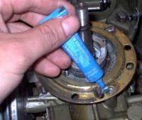
I habitually use blue loctite on the magneto plate screws on final assembly. It certainly wasn't there originally but I think the consequences of having one of these screws rattle loose is bad enough to warrant it.
|
|
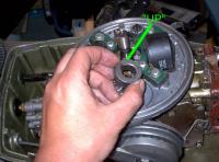
Normally the point's rubbing blocks are lubricated by a wick; a felt, oil soaked wiper attached to one of the ignition coils. If that is present, renew it with a few drops of light oil. If there is no wick present, lubricate the outside of point's cam with a light coat of high performance moly grease. Install the cam making sure the word "Top" faces upward.
Clean the crankshaft taper and the taper socket in the flywheel perfectly with a rag dampened with acetone or brake cleaner. There cannot be a trace of grease or oil on these. Then install the flywheel, the hub screw cover, and the flywheel nut. Using a large strap wrench to counter the torque, torque the flywheel nut to 35 ft/lbs.
|
Install the flywheel.
|
|
Link and Sync
|
(Check the next two entries for photos)
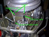
Once the engine is assembled it's time to adjust the linkage. The object here is to synchronize the spark advance with the carburetor. You want it adjusted so the throttle plate on the carburetor just begins to open when the mark on the follower's cam is just to the left of the black plastic follower.
To determine when the throttle plate is actually opening, you'll need to attach an indicator to the throttle shaft on the carburetor. A simple and useful tool for this is simply an alligator clip with a slight nail, stick, or bit of wire attached. Clip this tool to the throttle shaft as indicated.
Once set up, simply advance the throttle slowly from full back until you just see the indicator move. Note the position of the mark on the cam in relation to the follower and adjust the cam in or out as necessary to correct. To adjust the cam, loosen the two bolts that hold it to the magneto plate with a 5/16" wrench.
Wear on the follower isn't a problem if it's not excessive and the magneto plate is tight. Check to see if the wear causes improper movement on the follower as you advance the throttle. If the wear groove is excessive or the cam pops into and out of the groove, replace the follower.
|
|
|
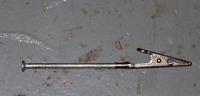
Here's the simple and effective indicator tool in all it's glory. A small nail turned out to be handy this time.
|
Indicator tool
|
|
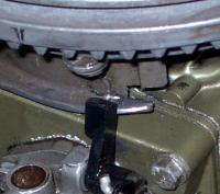
Follower position
|
This picture is wrong. You want the mark just to the left of the follower. Will update.
|
|
Install the spark plugs. They should be torqued 18 to 20 ft/lbs, but since the bottom one must be installed with a wrench this will be impossible. Rather tighten the plug until the gasket on it is snug. For fresh plugs it will be quite a bit of turning past finger tight - about 1/2 a turn. You'll feel the crush washer bottom out and the plug will become hard to turn. Stop there. For old plugs you'll have to use your best judgement. But be very careful as it's easy to strip the aluminium threads in these heads.
Run the engine in water up over the seam between the lower unit and mid-section.
After a couple warm up and cool down cycles, you'll have to retorque the cylinder head to 70 inch/lbs. Since the bottom two bolts are inacessable, you'll have to use an extension. A 7/16 combination wrench or 3/8-7/16 wrench can be employed with a 3/8" torque wrench, but the torque will be magnified. With a couple careful measurements you can torque these accurately.
Carefully measure the distance between the centre of a head bolt when placed in the wrench to the centre of the other end of the wrench. Mine measures 6.5".
Next measure the torque wrench. There should be a mark near the centre of the handle of the wrench. If not sometimes there is a differently knurled ring or some sort of indication. If none of that is present, make a mark at the centre of the torque wrench's handle. Carefully measure the distance between the centre of the square drive on the torque wrench and the mark or center of the marks on the handle. Mine measures 9.875 (7/8) inches. Now calculate the torque:
Setting = 70 inch lbs x Torque_Wrench_Length / (Torque_Wrench_Length + Extension_Length)
In my case:
Setting = 70 x 9.875 / (9.875 + 5.5)
Setting = 70 x 9.875 / 15.375
Setting = 70 x 0.642
Setting = 45 inch/lbs
So set the wrench to what you calculate, and then place the wrench on it's square drive. It is absolutely critical you then ratchet the torque wrench until the extension you've put on it appears to be straight with the body of the torque wrench, as it appears in the photo. Then simply torque the lower bolts.
I hope this can be of some service, and good luck with your 4hp! If you have any questions or comments, don't hesitate to email me at paul.moir@gmail.com.
|
Retorque the head
|
|