|
Picked up motor from Fed Ex Depot
|
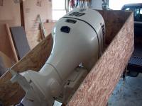
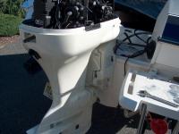
Here it is. A 2003 Johnson 90 hp w/power tilt & Trim from 1outboard.com. To save on shipping costs, I had the motor shipped to a near by Fed Ex depot. Fed Ex loaded the outboard onto my pickup truck, and that saved the extra cost of home delivery. The motor was packed very well and arrived undamaged at the depot. The motor was wrapped in black plastic wrap, but it has been removed for the photos.
|
|
|
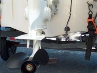
Motor is bolted to crate using the Transom Bracket mounting holes. The steering link is bolted to the crate, so the motor can not move on its steering pivot. That means the motor is supported by the strongest part of the motor, and held in place using all factory high stress point mounts and not just laid on its side and strapped tight like other shippers do.
|
Good packing
|
|
Gear Case strapped
|
The gear case is strapped down tight. The good packing job is why the motor arrived in great shape. No scratches, nicks, dings or damage. Good packing by 1outboard.com.
Unfortunately, the VRO oil tank and prop thrust washer/nut were not included. After speaking with Cyndy at 1outboard, they credited me for the oil tank (I found I had a spare!) and will send the thrust washer. Minor issues but still unnecessary mistakes attributed to Mike Jr not writing down the details of the sale.
|
|
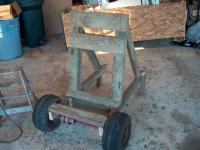
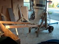
The Force motor has to come off the boat, and I want to be able to run it for buyers. I made this rolling stand to store the motor on, and it will also let me run the motor when needed.
|
Stand for Force
|
|
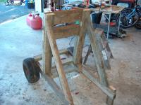
Another view
|
The stand is made from left over pressure treated lumber from other projects. Its been stored outdoors, that is why it looks weathered.
|
|
|
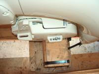
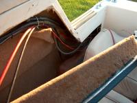
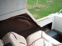
Just behind the fuel tank are the lower mounting bolts for the Force outboard. To remove those bolts, the gas tank must come out.
|
Prep to remove Force
|
|
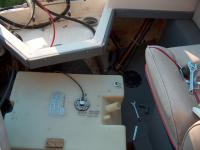
Tank and bolts out.
|
Tank is fully removed giving complete access to the bolts. The bolts were removed and now just the top clamps are holding the motor on. The tank will be left out until after the new holes are drilled and Johnson is mounted.
|
|
|
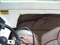
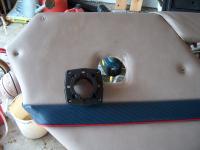
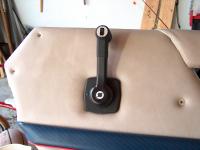
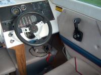
The side panel is removed in order to remove the Bayliner control (it is a Teleflex-Morse unit). This also gives access to the control cables and wire harness that must come out.
|
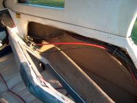
Bayliner Control
|
|
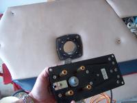
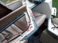
Access to Control Cables
|
Looking aft, the cables and wire harness can be removed easily.
|
|
|
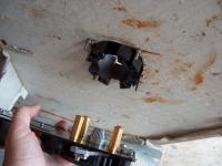
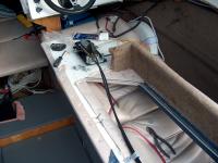
The Bayliner control is removed, along with the cables and wire harness. Now the wire harness and new control can be installed.
|
Control Out
|
|
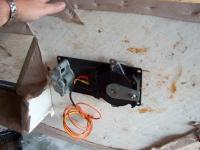
Force is almost ready to remove
|
At this point, the wire harness with ignition key, throttle and shift cables, battery cables and lower mounting bolts are disconnected from the boat. The steering cable is still connected, but it can not come out of the steering tube until the motor is actually off the transom due to space limitations.
|
|
|
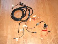
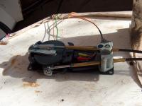
I bought this wire harness second hand through boat "for sale" forums. The three connectors at the top of the photo are the motor end of the harness, the connections at the bottom are the cabin end of the harness. Note new ignition switch with safety lanyard. It will give a little more safety when I am out on the water alone. I labeled some wires to make it easier to connect after installing.
|
Wire Harness
|
|
Installed Wire Harness
|
The Johnson wire harness has been installed. It is tie-wrapped to the steering cable, same as other wires and speedo tube.
|
|
|
The harness follows the steering cable, and runs back to the transom on the starboard side.
|
Harness snakes around.
|
|
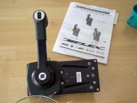
New Uflex Control
|
This is the Uflex control with Tilt/Trim and Warm Up features. It has a heavy cast aluminum lever and very thick steel frame with a few composite pieces around the lever. It looks and feels much better than I thought. Had to read the instructions over and over to determine which configuration to use for the Johnson (push throttle, pull forward gear) because Uflex is an Italian company, and the translation was so-so.
|
|
|
Here the front side of the control can be seen.
|
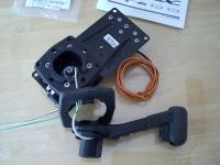
Control Apart
|
|
Installing Control
|
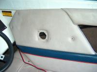
The Uflex control needs a larger hole in the panel than the old Morse unit. The side panel is plywood and the hole was enlarged using a sable saw with scroll blade.
|
|
|
Front of control is through bolted to the panel using supplied stainless hardware.
|
Intsalling Control
|
|
Installing Control
|
The back side of the control slides into the front half, and gets bolted in place.
|
|
|
Control is through bolted from the front side.
|
Installing Control
|
|
Control is mounted
|
Dress cover and lever installed.
|
|
|
Bayliner tie-wrapped the throttle and shift cables to the steering cable. But that makes it hard to remove the side panel. To make it easier to remove the side panel in the future, the cables are being attached to the side panel. PVC pipe strap makes a great support for wires, cables etc
|
New Cables
|
|
Connecting Cables to Control
|
The cables are connected to the control. The cables are secured loosely to the side panel because they move side to side about an inch or so when in use. Instructions say not to fix firmly closer than 20 inches to the control. The PVC pipe strap holds them loosely to allow some flexing and reduced cable wear.
|
|
|
The control cables are installed, and the tilt/trim and neutral safety start wires still need to be connected.
|
Control Connections
|
|
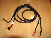
Battery Cable
|
A battery cable came with the used wire harness. Its a 10 foot long OMC cable for use with the 90 hp motor. The cable was covered with grease and dirt. It was washed with hot water and lots of dish detergent, then dried and inspected for cuts or damage to the insulation. I could not find any cuts or punctures in the insulation so it got a wipe down with Armor All to protect it from UV rays and salt exposure. Its now ready to install along with the outboard motor.
|
|
|
The side panel is fit back in place. The helm end of the wire harness with ignition switch and gauge connections can be seen under the dash.
|
Pannel Back in Place
|
|
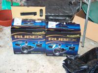
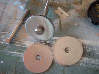
New Propeller
|
New Solas propellers were ordered for the new Johnson. Chose the Rubex line props because they have been getting very good reviews, and the hub is interchangeable with other brand props.
|
|
The 19 pitch prop is test fit to the prop shaft and gear housing. Looks to fit right.
Well, that is about it for the props until the boat hits the water.
|
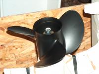
Test Fit
|
|
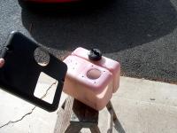
VRO Oil Tank.
|
A used oil tank is saving a good chunk of cash (about $200+ new, this one was $50 used). The pickup is removed from the tank to ensure that the low oil float switch is working. The tank needs to be washed out because there is a heavy build up of crud in the bottom of the tank.
Again, paying attention to details will prevent problems with oil starvation later on.
|
|
|
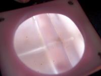
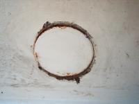
This photo is looking through the oil pickup hole in the tank after cleaning. About 2 cups of gasoline were put in the tank, then "swished" around until the layer of crud on the bottom came free. All the junk was poured out and two more cups of gas were added again. After sitting for about an hour, it was swished around and dumped. The tank is now nice and clean inside. The dark spots are ground in dirt on the outside of the tank that won't come off with cleaner. Maybe fine sand paper will clean it up.
|
Inside the Tank
|
|
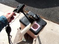
Prep Oil Tank
|
The "sock" filter on the pickup tube was removed and cleaned. But I just don't feel good about how clean it really is. I'm afraid that small particles of dirt or oil sludge will clog up the VRO pump and make the motor run lean on oil and cause severe damage.
I called the local BRP dealer and they have new filters in stock at less than $9 each. A small price to pay for clean oil and some piece of mind.
|
|
|
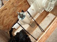
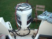
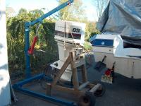
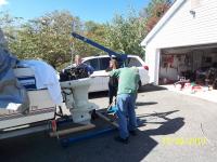
Lifted off the Force using a rented engine hoist. There are no lifting eyes on the powerhead, so rope was tied around the motor and used to lift it. Then motor was set on the stand and bolted on.
|
Off with the Old
|
|
Moving Outboard Stand
|
The outboard stand is now very heavy, as the motor weighs almost 280 lbs. A coupld of 2x4's tied on allows me to move the stand around like a rickshaw.
|
|
|
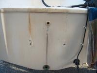
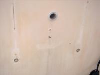
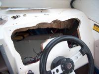
This is what the transom looked like after removing the Force outboard. The lower bolt holes have to be filled with epoxy and the drain tube from the splashwell is broken on the splashwell side and needs to be replaced.
|
Transom needs work
|
|
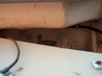
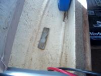
Damage from Force
|
The Force outboard used C clamps to hold the motor to the top of the transom. Tightening and re-tightening these clamps over the years started to cut through the fiberglass splash well. The cut is not all the way through, so the groove is filled with thickened epoxy.
|
|
|
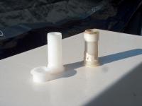
The new drain tube is an exact replacement for the broken one on the right.
|
Drain Tube
|
|
Transom cleaned up
|
The new drain tube is in place and sealed with Boat Life sealer. The lower bolt holes were drilled slightly oversize to remove any remaining sealer, and then filled with thickened epoxy.
|
|
|
Found these large 3" diameter washers in 18-8 grade stainless. The are used on the inside of the transom and doubled up for strength.
|
Stainless Hardware
|
|
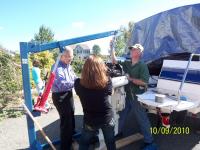
Motor on Hoist
|
Lifted the motor from the crate with the hoist. Here we are balancing the motor on the skeg while the chain is adjusted so the motor hangs vertical. At about 340 lbs, the motor does not balance easily, and it takes a few hands to keep it vertical while the chain is adjusted. That is my Wife and Dad lending a hand to keep the motor balanced.
|
|
|
Motor up, motor down, to the left, to the right, etc. Eventually got it where I was happy, and marked the bolt holes with pencil. Then drilled.
|
More Adjustments
|
|
Bolted in place
|
The bolt holes marked and drilled, and then the motor is bolted on using stainless hardware and lots of sealant for the bolts.
|
|
|
Prop height is going to be about 1" or so higher than the bottom of the hull when the motor is trimmed out to its normal cruising position.
|
Prop Height
|
|
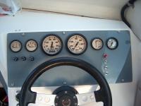
New Gauges
|
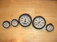
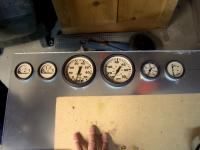
The Johnson uses the System Check system to monitor the motor, so I chose a new set of gauges that support System Check and the special connectors on the wire harness. The gauges are Fuel, Volts, Tach, Speedo, Trim and (not shown) Water Pressure.
|
|
|
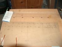
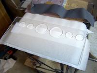
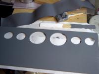
To install all the new gauges, a new dash panel is needed. The new panel is 1/4" clear Polycarbonate. The gauges were laid out on a cardboard mock up of the dash, then the dimensions transferred to the Polycarbonate to have holes cut for the gauges.
|
Start on New Dash
|
|
Cutting Gauge Holes
|
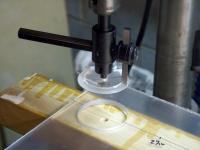
The gauges fit in 2-1/16" and 3-3/8" holes. A Circle Cutter was used to get the precise size holes, and prevents having to buy specific size round hole saws.
|
|
|
The holes are cut using the Circle Cutter about half way through, then the polycarbonate is flipped over and cutting continues from the other side. This method leaves a nice clean hole. The plug that comes out has tapered sides and is rather sharp.
|
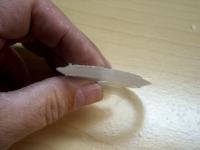
The Hole
|
|
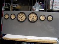
Gauges Test Fit
|
After cutting all the holes, the gauges are dropped in to check for proper alignment. There is less than 1/16" play in each hole, so it is important to drill the holes in the exact correct location.
|
|
|
The panel was clamped in a vise and the edges hand block sanded with 80 grit, then 150, then 220 grip sand paper. The corners are rounded off, and the edges rolled over all around. The 220 leaves a satin finish around the perimeter.
|
Sanded and Ready for Paint
|
|
Paint
|
The back side of the panel had the protective plastic peeled off, and then the first of a few coats of gray Rustolium paint. I tried to match the gray Deco Dot floor color, and a piece of the Deco Dot vinyl flooring is next to the panel for comparison. Pretty close!
|
|
|
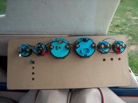
Test fit the gauges to the new holes.
|
Fitting Gauges
|
|
Cardboard Protection
|
A sheet of thin cardboard is cut to cover the back side paint and protect it from scratches. The holes were drilled for switches and fuse holders, and the night illumination wiring is done.
|
|
|
The new gauges needed some of the dash cut away.
|
Modify Dash for New Gauge Panel.
|
|
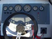
Panel Installed
|
The gauge panel is installed, and wire connections are being made.
|
|
|
Drilled a hole and installed the ignition switch. IThe old panel had the ignition on the left and under the wheel where it was hard to operate. Now its on the right and easy to access.
|
Ignition Switch
|
|
Relocating Batteries
|
The two batteries are being reloaced to the cuddy V-birth storeage compartments. This will make room in the rear for the oil tank that the Johnson needs. This photo shows a support block epoxied in place in the port compartment to support a battery platorm.
|
|
|
Starboard compartment with a battery platform fit in place. The platforms are made from 1/2" pressure treated plywood and coated in polyester resin for extra protection. A new battery switch allows switching between 1, 2, both or off. The battery box will be screwed to the platform.
|
Battery Platform
|
|
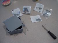
Junction Box
|
A junction box is needed to connect the battery feed cables to the outboard motor cables. A simple junction box is made from a outdoor grade PVC 2x4" box, some epoxy and stainless hardware.
|
|
|
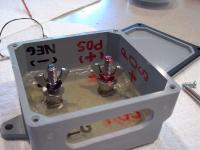
Two stainless steel 5/16 x 2" carraige bolts are used for the studs. The sides of the heads are ground flat so they will not spin in the epoxy. About 3/8" is cut off the end so the bolts fit inside the box, then 4 ounces of epoxy is poured in. Note that the epoxy got so hot that it expanded a bit around the parimiter. But the bolts are held in tight. A couple of nuts, washers and wing nuts complete the hardware. Cut a 3/4" wide slot in the bottom to feed the 4 AWG cables through. And labeled the posts Positive and Netagive to prevent accidental crossing of cables.
|
Assembled Junction Box
|
|
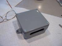
Cover on box
|
Cover has foam seal to prevent water from leaking in. The screws that came with the box will be replaced with stainless screws. Now it can be screwed to the transom where needed to connect the battery feed to the outboard motor cable.
|
|
|
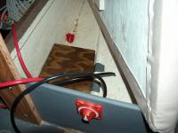
Junction box is mounted on the transom on the starboard side.
|
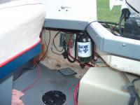
Junction Box Installed
|
|
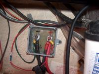
Junction Box Connections
|
Took this photo with the cover off to show that more than one set of cables can be connected in a large box like this.
|
|
|
The oil tank was installed on the port side. Ready for break-in!
|
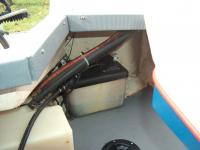
Oil Tank Installed
|
|
Motor Problems
|
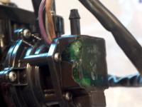
Took the boat to the bay for the break in procedure, but things did not go well. The OMS pump was sending an alarm and warning light to the System Check lights. Turns out the VRO fuel/oil pump was damaged. The pump had impact damage to the computer chip circuit that monitors the oil flow and mix. Its visible as chipped corner and green plastic missing.
|
|
|
After talking with Mike Jr for a while, Chad the shop foreman was put on the phone, and after a minute or two describing the problem, he said to return the pump. This photo shows the damage to the pump.
|
Another view of bad pump
|
|
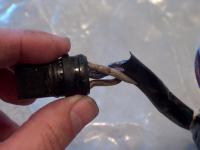
Bad Wires
|
This photo shows the wire harness that is part of the OMS pump. The plastic sheath is so brittle and hard it has cut right through the insulation on the exposed wires.
|
|
|
Chad had a brand new pump drop shipped from their BRP supplier. Interesting warning on the box top about the warranty not covering ethanol damage. Especially in the face of impending legislation that will increase the ethanol level to 15% (from the current 10%) in the fuel we buy at gas stations (which is where I fuel up this trailered boat)
|
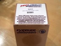
New Pump Arrives!
|
|
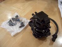
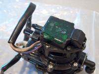
Whats in the Box.
|
Here it is. A brand new OMS (aka VRO2) pump. It comes with an assortment of elbow fittings so it will fit either the V4 or V6 model motors. The pump was installed then the motor was test run at a local lake. Everything was OK for about 45 minutes then the ignition started acting up and the motor died. Installed larger fuel lines (3/8") and new filter, but three trips afterwards had the same problem of stalling after about 45 minutes to an hour. Frustrated, I put the boat away for the winter.
|
|
|
(Insert New Description)
|

(Insert New Caption)
|
|