|
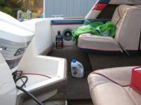
Limited Space
|
The 1600 Capri has limited space for gear, let alone additional fuel tanks for long trips.
|
|
|
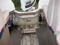
The tight space compounded by an angled splash well makes it hard to find a tank that fits.
|
Side View
|
|
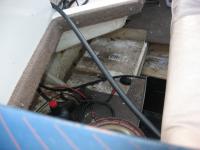
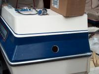
Tank Location
|
This is where the portable tank was, and where the new tank will be permanently mounted.
|
|
|
Now for the hardware! I had to determine if the tank will fit in the boat based on the information in this schematic. I measured the tank area in the boat on 3 different occasions to make sure it fits. This tank has an angled fill neck that allows the tank to be tall and not have clearance problems with the splashwell overhead.
|
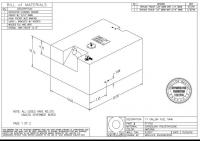
Moeller 1701 Tank Specs
|
|
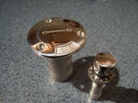
Stainless Steel Fuel Fill and Vent
|
Sea Dog makes this really nice cast 316 stainless steel fill plate. With a screw on fill cap and O-ring seal, its water tight and will keep looking good for years. Used this same one on my MFG so I know it works really well. Coast Guard regulations specify that the fill cannot be located where an over-fill will let gas run inside the boat. So it will get mounted on the back side of the transom for ease of fill and to meet CG regs. The vent is also cast 316 stainless steel. Both of these parts will look like new for years in the salt water environment. Chrome plated zinc equivalent parts will last two years tops.
|
|
|
These two parts are very high quality. Beautifully polished, heavy castings, and the gas cap comes with a stainless safety chain. A nice feature to have when dropping the cap means it goes to the bottom of the bay.
|
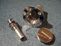
Safety chain on cap is nice touch.
|
|
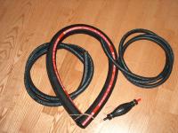
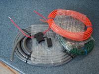
Hoses
|
These are the hoses needed to complete the project. A 1-1/2" fill, 5/8" vent, and 5/16" fuel line. Also need a 5/16" primer bulb with stainless steel check valves and stainless banding to prime the motor.
|
|
|
This Moeller filter is similar to the Racor filters but at a lower cost, and it has a composite head so it won't corrode in the salt. Water collects in the bowl underneath and can be drained out through the petcock. This filter head accepts a standard size filter, so in a pinch a replacement filter with or without the filter bowl can be used. Only Racor filters will fit the Racor head, and at greater cost. Best to be safe with the Moeller unit.
|
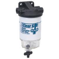
Water Separating Fuel Filter
|
|
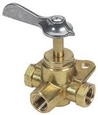
3 Way Fuel Valve
|
This popular Moeller 3 way fuel valve will allow the fuel line to be shut off during periods of storage. A portable fuel tank can be connected after a standard fuel connector is attached to one of the valves ports. Again, I'm using the same parts as I did when doing the MFG fuel tank. I prefer to go with what I know works well.
|
|
|
Came home from work and found the Moeller tank had been delivered. It came with the better quality WEMA fuel sender, all fittings and two aluminum mounting brackets. This tank was designed for a specific model boat so one of the two mounting brackets won't work for this application. It will probably end up being installed with tie down straps.
|
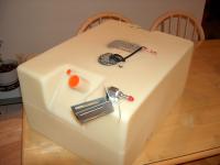
Fuel Tank Arrived!
|
|
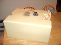
Another View
|
Tank sure looks big sitting on the kitchen table. Had to double measure to be sure it matches the specs, and it did.
|
|
|
The boat has the hard top on it and a cover, so even though its cold and it snowed, I can still work inside the boat. The cover lets in plenty of light.
|
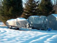
Working in Winter
|
|
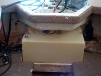
Tank in Place
|
Tank fits very nice in the space where the old 9 gallon tank fit. And the filler neck clears everything. Hard to tell from the angle of the photo, but the neck is exiting the splashwell while still under the transom, so none of the fill hose/pipes will be sticking out. Also, only a small portion of the tanks corners extend past the splashwell, no more exposed than the old tank. That makes it easier to build an enclosure to hide the tank. Note location of the fill and fuel line connector.
|
|
|
Although the tank fits nice, there is a small problem. When the fuel connector is at the rear so the fuel pickup tube is still able to suck fuel when its almost empty, the fill fitting does not clear the splaswell!!! I took the fuel line connector off (its laying on the tank) to fit the tank in place. To make this work, either a low profile fitting is needed, or a bump will have to be added to the splashwell to clear the connector. Right now I don't feel like cutting into the splashwell, so maybe I can find a low profile fitting, or get a longer fill tube so it will extend to the rear of the tank when mounted as in the previous photo.
|
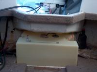
Tank Reversed
|
|
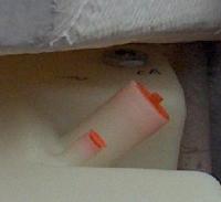
Clearance problem
|
Close up detail of the clearance issue. Grrrrr. Anyway, after much go around on ideas, I finally decided it is better to just cut a hole in the splashwell to get the clearance needed.
|
|
|
The plan is to cut a 2" hole in the splashwell and install the fuel pick up tube through the 2" hole to make installation easier. A slightly raised cover will be needed to cover the 2" hole. So I picked up this 4" round outdoor PVC electric box. It should make a nice deck plate. I'm not using an "off the shelf" deck plate because they are sit flush/recessed, and the splashwell is curved in that area. So the common deck plate would need a lot of modification work.
|
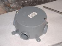
Making a custom deck plate
|
|
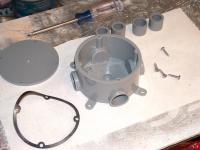
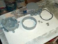
What came in the PVC box
|
Here is what came with the PVC box when I opened it. More screws, some plugs, and a rubber gasket for the top. All I need is the top inch or so of the box to make the deck plate.
|
|
|
Cut the bottom off using a hand saw. Masking tape was used to make an even cutting line around the box. Worked very well. A little sanding to remove the burrs and its starting to take shape.
|
Cut off bottom.
|
|
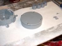
Finished Deck Plate
|
Sanded, some excess flasing was removed with razor knife and this is the finished product. Only a total of 1 inch tall. The screw bosses (see previous picture) extend the full height of the piece, so it can be screwed in place from under the splashwell. It will need a little more contour sanding because the splashwell is slightly curved where it will be attached. A little Boatlife sealer and it will be done.
|
|
|
Cut the access hole using a 3" hole saw. Now the fuel pickup tube and fitting can be installed in the tank.
|
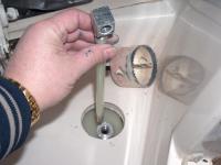
Cut hole in Splashwell
|
|
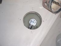
Pickup and hose barb
|
The pickup tube is in place, and there was enough space to screw in the hose barb from above too.
|
|
|
This view from below shows that the hose barb is close to the splashwell, but still enough space for the fuel hose and a clamp and still not touch the splashwell. The 90* fitting is just hand tight, so it will be lower after tightening with a wrench, and if more clearance is needed, the bottom of the splashwell can be ground away right over the hose barb. There is 1/2" plywood core in the splashwell so there is material to work with.
|
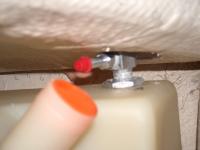
Enough space for hose and clamp
|
|
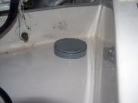
Deck Plate attached
|
The deck plate is screwed on from below. The splashwell is curved in this area, so the deck plate had to be sanded with a small disk sander until it fit the contour of the splashwell.
|
|
|
The deck plate is hardly noticeable. Might not even bother to paint it.
|
Hardly noticable
|
|
Cutting holes
|
Cutting holes is always the scary part of working on the boat for me. I measure five times to be sure! It was a nice surprise to see how thick the cap on the boat is at least a full 1/4" of fiberglass. I was afraid the hull would need reinforcing with plywood behind it, but now I will through bolt it with bolts and locking nuts rather than wood screws.
|
|
|
The fill and vent are trial fit and the hoses connected. The vent is higher than the tank as per CG regs. The vent hose loops up over the top of the fill and back down to the tank. The loop prevents water from entering the gas tank through the vent.
|
Fill and Vent Trial Fit
|
|
Wire Supplies
|
Ordered some wire supplies for the project. The green is for bonding (grounding) the fuel fill and vent as per CG regs, the orange is for the fuel gauge, and the grey is for a bilge pump that will be added too. Because this boat will be used in salt water, all the wire ordered is tinned marine grade to resist corrosion.
|
|
|
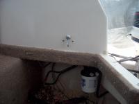
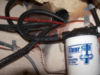
Mounted the fuel filter to the side of the plashwell under the gunnel. Through bolted with 3/8" stainless carriage bolts and locking nuts. The battery box mounts to the left of the filter with plenty of space to reach in and change the filter cartridge.
|
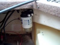
Fuel Filter Installed
|
|
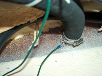
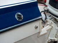
Fill hose
|
Fill hose connection to fuel fill from inside transom. Fuel fill is attached with screws and locking nuts with washers, sealed with Boatlife sealer. Very solid and rigid. Notice double stainless clamps, and green bonding wire as required by Coast Guard regulations. Also note that the fuel vent line loops above the fill before returning down to the tank.
|
|
|
Had to cut out some of the foam in the top of the transom so the vent hose could be routed uphill over the fuel line. This makes it harder for water to get into the tank through the vent. Stainless vent is also bonded with the green wire.
|
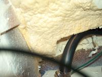
Vent Hose
|
|
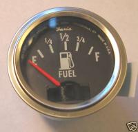
Fuel Gauge
|
Ordered this new gauge from ebay. It was very inexpensive and will do the job. Just doesn't light up.
|
|
|
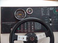
Existing dash. There are pre-labeled areas for additional switches and gauges.
|
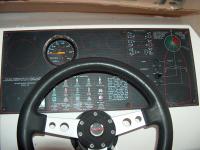
Dash Before
|
|
Dash After
|
Gas gauge, bilge pump switch, and windshield wiper switch. Also have an extra new switch to replace the black toggle for the navagation lights so they all match.
|
|
|
Of course, there is a big block of foam right where I wanted to put the 3 way fuel valve. Foam is not easy to remove, but using a 3" hole saw in the cordless drill made things a lot easier. Here the round hole saw marks can be seen where the foam was removed. This shot is taken looking straight up from the floor under the transom cap.
|
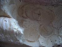
More Foam Fun
|
|
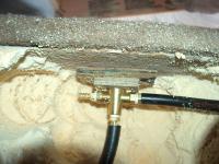
Fitting Valve
|
A 1" spacer block was made by gluing up 2 piecesof 1/2" pressure treated ply. The block keeps the valve handle from sticking out too far. Again,this is looking straight up under the transom cap. The line on the right is from the fuel tank, the line goind down goes to the filter, and the barb on the left will have a Johnson male portable fuel tank connector on it for connecting a 6 gallon portable if extra fuel capacity is needed. All hoses will get hose clamps after final fitting.
|
|
|
Here it is. Straight up is OFF, to the right is ON - main tank, to the left is ON - Aux tank.
|
3 Way Installed
|
|
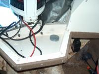
More Fuel Lines
|
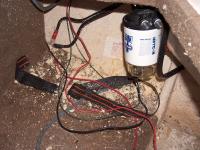
This photo shows how the fuel lines enter and exit the filter, then pass through the boot out to the splashwell and outboard.
|
|
|
Secured wires and fuel lines with plastic plumbing strap. It is flexable, won't rot, takes a big load, and I could not break it with my bare hands.
|
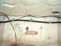
Wire and hose
|
|
Shredded foam Everywhere
|
Cutting out the foam made a real mess. There are little bits of shredded foam all over the boat. They stick to everything with static electricity.
|
|
|
Tank connections are done. Again, double stainless clamps on the fuel hose.
|
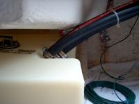
Tank Connections
|
|