|
(Insert New Caption)
|
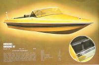
Here is a 1971 brochure page showing the GW Invader Banchie and its particulars...
|
|
|
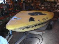
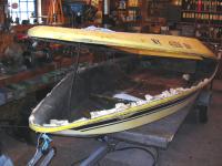
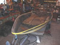
November 17, 2007. Thought I had a picture of it as I received it, but I can't find it. Here's one just after I had removed the rub rail.
|
(Insert New Caption)
|
|
(Insert New Caption)
|
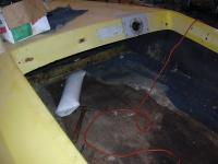
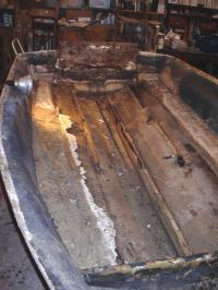
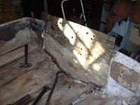
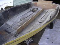
Here's a shot of the interior. Floor is loose and deteriorated. The metal piece on the dash with the large hole in it is a patch that was made to brace up the broken dash board.
|
|
|
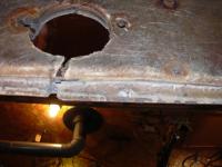
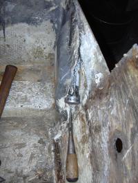
A close-up view from under the broken dash board. Looks like someone sat on the dash at some point...
|
(Insert New Caption)
|
|
(Insert New Caption)
|
This was my first dilemma. I had to remove the deck from the hull in order to properly replace the transom and floor sections. They were assembled "shoe box" style with an overlap between the deck and hull sections. Well, the deck and hull were glassed together with a layer of cloth, combined with a layer of chopped glass. It was too thick and too well applied to just peal off. Plus, someone had apparently tried to patch a crack or leak at the seam with MORE glass gunk.
|
|
|
And proved difficult with a specially ground chisel. This was my progress after about an hour of banging away. All of 18-inches! Plus, some scraped knuckles, bashed fingers and general crankiness on my part.
|
(Insert New Caption)
|
|
(Insert New Caption)
|
Plus, there was NO WAY I was going to make this method work up under the tight space of the bow - I'm 6'4" and had a hard enough time twisting my way under the gunwales to do what I did get done...
|
|
|
November 18, 2007: The easier way!! After calling it a day on Saturday, I pondered the issue a bit and came back ready to do battle on Sunday. Came up with a different plan - attacking the seam from the OUTSIDE. I discovered that if I drove a wide chisel up into the seam between the deck and hull sections I could tear the inner glass loose a bit. I worked my way around the boat three times, each time loosening it up a bit more until the inner glass tore completely away from the seam!
|
(Insert New Caption)
|
|
(Insert New Caption)
|
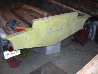
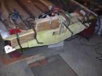
After breaking it loose, I lifted the bow section up to put some tension on the transom board to transom well connection, which was still partially attached. Kinda looks like a big "Pac Man", or a jaundiced alligator - not sure which...
|
|
|
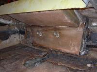
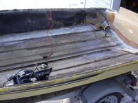
Here you can see the transom area. Looks like someone had done a replacement at some point with one of the pour-in-place type transom products. A little prying with a crowbar had it loosened up enough to break free.
|
(Insert New Caption)
|
|
(Insert New Caption)
|
Now I'm just waiting for another set of hands to help me carry the deck outside so I can get going on the rest of the deconstruction...
|
|
|
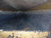
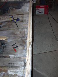
Here's a shot of the forward tip of the keel, just ahead of the kickboard. Completely rotted and crumbling.
|
(Insert New Caption)
|
|
(Insert New Caption)
|
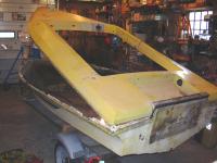
November 24, 2007: Found some help this morning and got the deck off! Also started cleaning up the loose fiberglass that was at the seam. Most of it peeled right off, with a little effort.
|
|
|
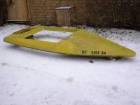
The topside deck, now residing in my driveway. Looks like a 'Flintstone' boat!
|
(Insert New Caption)
|
|
(Insert New Caption)
|
With the deck off I was able to check out the transom area a bit better. Looks like someone did a repair at some point with one of the pour-in type kits. Didn't do a good job of it, as they didn't get all the old wood out, and only went down about halfway to the bottom. Part of the core is still stuck to the transom well.
|
|
|
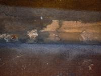
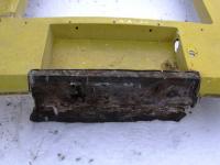
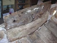
Here you can see the remaining rotted wood from the original transom. Can't imagine this transom holding 80 horsepower, even when new! It was only 1.5-inches thick for the top 10-inches, 3/4-inches thick for the rest of the depth, and didn't go full width to tie into the sides. The rebuild will be MUCH beefier!
|
(Insert New Caption)
|
|
(Insert New Caption)
|
The floor came out relatively easily as everything that tied it in was either cracked or no longer stuck to it. Pretty sure someone replaced the floor at some point.
|
|
|
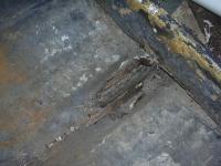
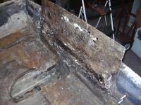
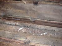
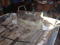
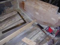
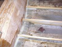
This is what was left of the keel and stringers BEFORE I dug anything out! Much of the core material was simply gone and that which was left was mush. The one "solid" looking piece in the lower left was a small chunk of replaced wood butted up against the rotted core of the stringer - which is what led me to believe the floor had been out before...
|
(Insert New Caption)
|
|
(Insert New Caption)
|
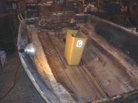
The bucket is filling quickly as I get the hull cleaned up.
|
|
|
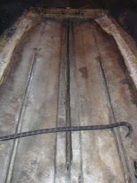
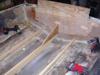
Got all the remaining stringer and keel core materials removed. Most came out pretty easily as the fiberglass skin had long since lost its bond with the core material.
|
(Insert New Caption)
|
|
(Insert New Caption)
|
November 25, 2007: Spent a good part of the afternoon cleaning up the inner skin of the transom. The big stuff went easy, but the bottom section is wedged in there pretty good.
|
|
|
A combination of chisels and wedges manages to rip the backing board for the tow eyes out. More wood core, more rot found...
|
(Insert New Caption)
|
|
(Insert New Caption)
|
Got pretty much all of it out! A little time with a sander and it'll be ready for a new transom core!
|
|
|
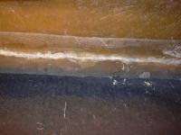
Discovered a 10-inch split in the transom skin, right where the poured in transom core met the rotted wooden transom core. I would imagine the transom flexed enough to crack it right along the border between the two cores. I will repair it and seal it up when replacing the core.
|
(Insert New Caption)
|
|
(Insert New Caption)
|
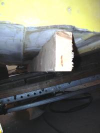
December 9: Although too cold to epoxy, I did get the first layer of the new transom cut and fitted this weekend. Also cleaned up the inner skin of the transom a bit more using 60-grit sandpaper and an angle grinder.
|
|
|
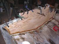
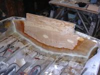
December 22: Warmed up enough this weekend to fire up the stove and do some epoxy work. A thick layer of epoxy mixed with 403 filler to a peanut butter consistency along with two layers of fiberglass cloth (to help fill the area where the crack was in the outer skin) made a good bed to clamp in the first layer of the new transom.
|
(Insert New Caption)
|
|
(Insert New Caption)
|
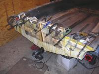
Lots of clamps to hold it all in place, but not TOO tightly, as I don't want to squeeze all the epoxy out. I also used some drywall screws with wide flat washers spaced around the lower portion to help pull it all together without dimpling the outer skin. The center board thing is a clamp extension to put some gentle pressure in the middle of the transom.
|
|
|
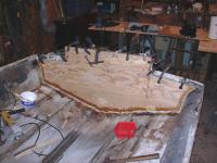
I took a chopped up glass fibers, mixed them with epoxy and jabbed it into the gaps between the transom board and the side and bottom edges. The edges will eventually be glassed into the side for strength. After curing, this transom is already stronger at one layer than it probably ever was at two!
|
(Insert New Caption)
|
|
(Insert New Caption)
|
December 30: Spent some time sanding the outer skin to remove the excess epoxy goo. The cracked area faired out nicely. It still needs a bit of touch-up to take care of the screw holes, etc., but it's looking much better.
|
|
|
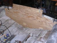
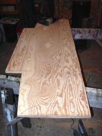
I rough-sized a section of plywood, clamped it to the outer skin of the transom and then traced the shape onto the plywood. I rough cut it on the lines then spent some time with a belt sander to get it fitted.
|
(Insert New Caption)
|
|
(Insert New Caption)
|
And voila! Second layer of the transom is ready to go in!
|
|
|
The new transom will be 1.5-inches thick full width, full height. I've used two layers of 3/4-inch Fir plywood, AB grade.
|
(Insert New Caption)
|
|
(Insert New Caption)
|
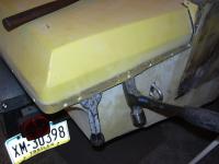
January 1, 2008: Lots of epoxy (West System #105 resin and #206 slow hardener) with filler (#403 silica) with a layer of 4-oz. glass cloth between them and the second layer of the transom is firmly seated. Not too much pressure on the clamps, though, as you don't want to skooge it all out. I ran a thick fillet of peanut butter epoxy into the gaps at the edges. Second layer went in much easier than the first, as the first layer took all the sagging and warping out of the skin. Needed fewer clamps and screws to seat it as it was a flat surface mating to a flay surface. This thing is rock solid now!!
|
|
|
Saran wrap over the clamping boards keeps things from sticking where they shouldn't. The boards help distribute the clamping power so that you don't dimple anything from clamp pressure.
|
(Insert New Caption)
|
|
(Insert New Caption)
|
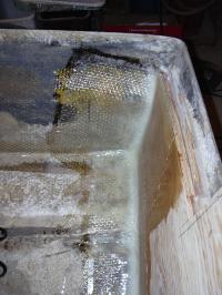
January 19, 2008: Took a couple weeks off to work on another project. Back to the boat! Got the transom glassed in. I used 2-layers of glass cloth, followed by a layer of woven roving.
|
|
|
A closer-up photo of one corner. I ran the glass about 8-inches up into the sides so it'll have a good bite.
|
(Insert New Caption)
|
|
(Insert New Caption)
|
January 27, 2008: Spent some time with the grinder today! First, I used the cutting wheel to trim the lip of the fiberglass at the grooves where the stringers and keel will be going in. Then, I swapped in a grinding wheel to fair out the existing glass about 6-inches either side of the stringers and keel so that the new glass will have something to bite when it gets epoxied in. I also rough cut an 8-foot chunk of 3/4 inch fir plywood for the keel. Lots of dust! Glad I did this outdoors - got to about 40-degrees today!
|
|
|
A good vacuum cleaner does wonders with removing the dust! Almost ready to start putting the structure back into the hull!
|
(Insert New Caption)
|
|
(Insert New Caption)
|
February 3, 2008: I decided to keep with original and go with fir planking for the keel. I modified the design a bit to tie the keel into the transom, with a notch for the drain plug.
|
|
|
I also made a knee to better tie the transom into the keel.
|
(Insert New Caption)
|
|
(Insert New Caption)
|
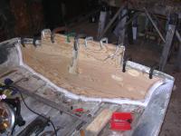
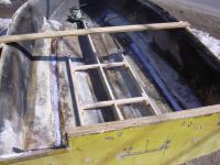
While fitting the stringers I couldn't figure out why my "straight" parts were rocking in their slots. A straight-edge on the bottom revealed several waves of hooks and rockers in the hull. I screwed two straight 2x4s to the bottom from the inside and it took the shape back to true!
|
|
|
Now that the bottom is straight, I installed the keel and stringers. They're lightly glassed in at the moment so that they'll hold the shape of the hull, but soon I will beef them up with heavier roving and mat. I wanted to get them in so I could remove the 2x4 braces from the bottom before proceding - don't want to glass over the screw heads!!
|
(Insert New Caption)
|
|
(Insert New Caption)
|
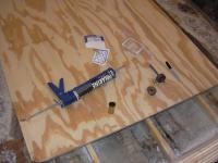
March 30, 2008 - I rough cut the floor this morning and decided to install the drain plug sleeve before I went any further and while the bottom of the boat was still fully accessible. Luckily, my Dad has one of the flaring tools to aid in installing the brass sleeve...
|
|
|
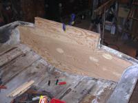
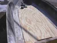
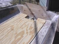
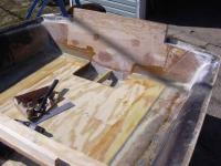
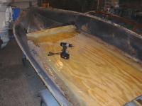
Floor is now fitted. Edges are tapered and sanded to better match the contour of the hull.
|
(Insert New Caption)
|
|
(Insert New Caption)
|
I also notched the rear of the floor to allow access to the drainage area and future installation of a bilge pump. Decided not to use the transom knee idea.
|
|
|
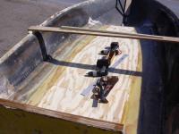
A good vacuuming of the interior and it's time to lay some epoxy peanut butter onto the stringers and crossmembers. The floor will bed into it and become pretty much a permanent fixture. The board across the top is an anti-spread bar I made up. I discovered that the hull had spread a couple inches without the deck in place. I didn't want anything I've been adding to take a set and make the spread permanent so I made up the bar to pull things back in line.
|
(Insert New Caption)
|
|
(Insert New Caption)
|
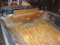
April 6, 2008: The floor is now glassed in with two layers of woven roving and a layer of 4-oz. cloth. Boat is ROCK solid now!
|
|
|
Rear view of the floor glassed in.
|
(Insert New Caption)
|
|
(Insert New Caption)
|
April 20, 2008: The floor is now completely sealed and glassed in. I used a single layer of 8 oz. cloth with West System rolled in. The epoxy seals it and the cloth adds abrasion resistance.
|
|
|
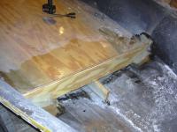
April 27, 2008: Installed the kick-board. Epoxied and glassed in place with cloth and mat.
|
(Insert New Caption)
|
|
(Insert New Caption)
|
Other side of the kick board...
|
|