|
Layout a mounting plate for the pump.
|
I'm using the 1.5" square OMC pump that is common to many outboards 4-15hp used between the early 70s and the early 00s. Despite it's small size, I could not modify one of the bypass covers to fit it nicely. So a mounting plate is employed
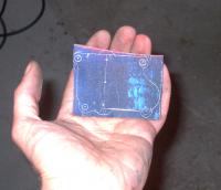
Lay out a piece of aluminium plate for mounting the pump which will attach over one of the bypass covers. You can see the four screw holes for the bypass cover bolts and the three lined up markings for the fuel pump between them. If you look close, you can see where I've added some 'ears' to the outline of the bypass cover to catch the pump mount screws. The centre mark is for the pressure pulse port.
I've used 3/8" aluminium plate that I had on hand, but 1/4" would work fine and is a lot less work. I would not go thinner than that because you won't be able to get many threads in it. 1/4" should give you 6 threads of the 10-24 screw which is just fine. There is an advantage to 3/8" though in that it fits the stock pump mounting screws for length.
|
|
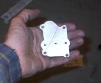
This step is purely cosmetic. If you don't care what it looks like just make the plate square.
Cutting out took a good 1/2 hour with a sharp hacksaw, a round and a flat bastard file. A good bench vice is essential.
|
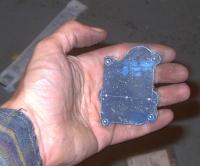
Cut it out.
|
|
Drill and tap it
|
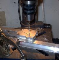
Drill the clearance holes for the bypass cover screws. I used a drill that matched the size of the holes in the bypass cover. Then drill the screw holes for the pump. These are #10-24tpi, which need a #25 drill. 5/32" is pretty close to #25 if you only have fractional bits.
For the pressure pulse port, start with just a small hole. You'll need a small drill to start the next step. I used the #25 because it was in the chuck.
Careful tapping the screw holes. These are deep so its absolutely critical you start the tap square. Back out often and clean the threads. Probably it would be best to do this step before even cutting out the plate!
|
|
Now you're committed. (Or should be!)
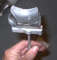
Temporarily bolt the mounting plate to the bypass cover, and use the hole you just drilled in the mounting plate to guide the drill in through the bypass cover. The 10hp cover is curved so this is virtually the only way to start the drill properly.
Jump ahead and have a look at the next step. To connect the pump and bypass cover an aluminium tube is soldered to the cover. Drill the bypass cover up to the outside diameter of the tube. A light press fit is ideal if you can acheive it. Drill the mounting plate a little larger so the tube slides easily through it.
|
Drill the bypass cover
|
|
Insert the tube
|
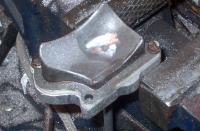
Push the tube in. If you don't have a press fit into the bypass cover, secure the tube temporarily somehow. If you don't intend to solder, simply glue it in with JB weld.
|
|
Grind the tube flush with the bypass cover, Then if you want to solder the tube the same as I did, grind the area around the tube a bit to expose fresh aluminium. I used a dremel with a course sanding drum for this.
A wiser man would probably just use JB weld, but I had some aluminium solder on hand.
|
Grind the tube
|
|
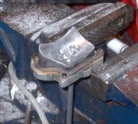
Solder the tube in.
|
|
|