|
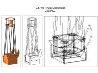
Rough Draft
|
An early version of my 3D model used moon-shaped altitude bearings. The torques for this particular arrangement left a deficit below the balance point. This is partly due to the rather long focal length of my primary mirror. Most 12" or 12.5" truss-dobs are f/5 or f/4, mine being a full foot longer than the former. I was forced to redesign the bearings and correct the imbalance.
|
|
This new bearing design solved several problems:
1. The balance point is raised three inches providing some much needed torque below and reducing torque above.
2. The bearings themselves are more massive and added some additional weight below the balance point, again increasing torque where it was needed.
3. A 'flare' was added that reaches up to cover the imaginary axis line. This point will hode an optical encoder linked to a set of Digital Setting Circles (allowing me to access a computer holding thousands of cataloged objects, then aim the telescope accordingly).
|
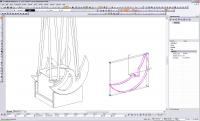
Revised Altitude Bearings
|
|
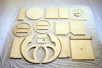
Wooden Parts via the CNC Router
|
I owe Jeremy Hudson and the staff of Prestige Casework a great debt of thanks for their assistance in cutting these parts. CAD drawings were uploaded and used to drive a very large CNC router. The results were exceptional.
|
|
|
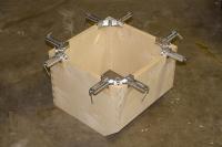
The alt bearings are 1.25" inches thick. Two pieces were cut to form each bearing, from 0.5" and 0.75" respectively. Here two halves are clamped and glued together to form a single bearing.
|
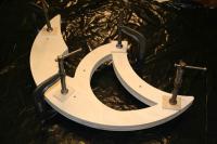
Laminating the Altitude Bearings
|
|
Assembling the Mirror Box
|
The primary mirror is held in the bottom of a wooden box, which will then have the altitude bearings fastened to either side. I spent a couple of hours scribing and cutting out the finger joint corners (round fillets were left by the router bit in each joint). The prepped sides went together smoothly. Material for this box is all 0.75" plywood.
|
|
|
The completed box with light baffle installed and lid.
|
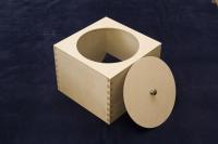
Completed Mirror Box
|
|
Completed Mirror Box
|
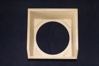
Inside view of the mirror box. Corner gussets are installed underneath the light baffle to strengthen the box. Some additional braces will be added later.
|
|
|
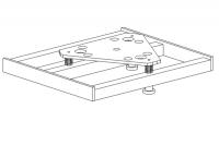
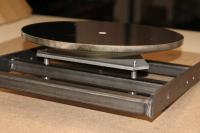
This smaller box will support the mirror box and allow the entire telescope to tip up and down via the altitude bearings. The bottom of this box serves as one half of the azimuth bearing, allowing the scope to be aimed left and right.
|
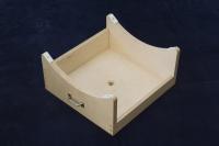
Completed Rocker Box
|
|
Supporting the Mirror
|
The first truss dobsonians featured a hinged hatch on the bottom of the mirror box called a tailgate. This component supports the mirror cell, adds necessary ballast, and strengthens the mirror box. In modern truss-dobs the tailgate no longer swings open, but rather serves it's purpose in a fixed position.
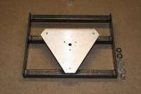
For my telescope I sketched a traditional steel-frame tailgate and designed an upper cell plate to support the conical primary mirror.
|
|
|
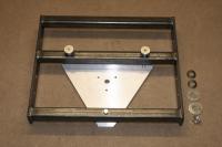
My tailgate is composed of three sections of 1.0" x 1.0" square tube (0.125" wall) and two sections of 1.5" x 0.25" flat bar. The metal pictured here cost $13 at my local supplier.
|
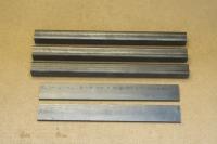
Building the Tailgate
|
|
Building the Tailgate
|
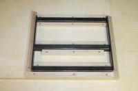
As I have learned the hard way, it is necessary to build a jig that securely holds each piece in the exact position desired BEFORE welding. This jig was taken to a local welder with the metal pieces already seated.
|
|
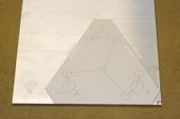
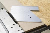
For budgetting reasons I abandoned my original plans to have the mirror cell water-jetted from aluminum. Instead I've improvised a low-tech method of cutting the desired shape and hole pattern using tools in my home shop.
Here I've printed out the CAD drawing at 1:1 to transfer the pattern onto the aluminum. Lines were digitized between hole centers for the sole purpose of scribing those points into the metal.
|
Fabricating the Mirror Cell
|
|
Fabricating the Mirror Cell
|
The outline was cut on a table saw. I drilled three additional holes to bolt the aluminum to a sacrificial piece of plywood that was ripped to be the same width as the template (measured from broad side to narrow side). The hardest part of setup was finding a fence that was thnner than the plywood jig so the metal could pass over it on the non-cutting side.
|
|
|
This made the whole process very easy. I ripped the metal along both sides of the plywood, then rotated the metal 60º (or one hole over) and repeated the cuts.
|
Fabricating the Mirror Cell
|
|
Fabricating the Mirror Cell
|
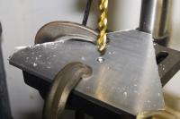
The holes for mounting the conical primary and collimation bolts were an easy job on my drill press.
|
|
|
Top view of completed (but unpainted) mirror cell.
|
Fabricating the Mirror Cell
|
|
Fabricating the Mirror Cell
|
Bottom view of completed (but unpainted) mirror cell.
|
|
|
Side view of completed (but unpainted) mirror cell with 12.5" f/6 Royce conical primary mirror installed. This combination tailgate/cell is currently a candidate for production and may be available to order from Optical Supports
|
Fabricating the Mirror Cell
|
|
First Light
|
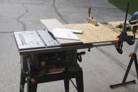
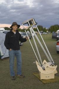
First light took place on November 12 at the 2009 Nova Sedis Star Party in Chiefland, Florida. The telescope is pictured here is about 90% complete and fully functional with a few minor quirks.
|
|
|
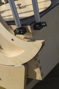
A descrete counterweight system will be added to the rear of the mirror box (pictured here) to help the scope stay balanced when aimed at objects low to the horizon. A simple computer will also be added to give "Push-To" convenience of entering an object and having the display prompt the user one where to aim the scope.
|
Planned Upgrades
|
|
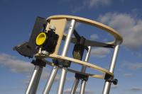
Planned Upgrades
|
Here the UTA is pictured with a Telrad finder (far left). I'm also going to add a 50mm finderscope which will mount between the Telrad and the focuser. The interior of the rings will be lined with Kydex which is currently being shipped to me. Last but not least, wiring will be installed to run the dew heater moutned behind the secondary mirror.
|
|