|

Inspired to Upgrade
|
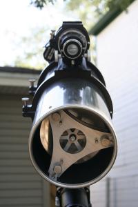
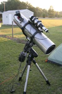
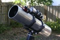
My former astrophotography rig consisted of a Meade SN8 imaging with a modified Canon 350D (pictured here). The guidescope (dubbed the 'SS Crapper') was my first feable attempt at ATMing. The SN8 was a great instrument for learning and provided me with many successful imaging sessions over the year that I owned it. This model is very heavy for its aperture though and collimation is a chore due to the poorly designed secondary holder. By all accounts I am still a beginner, but eventually these issues and more became the limiting factors rather than my own skills. I've outgrown the limitations of this equipment and the 8" F/5 astrograph I'm building will represent an upgrade in every single category.
|
|
|
NEWT 2.5 is a free ray-tracing application that allows the user to layout a classic newtonian telescope. Thanks to some guidance from others more experienced than myself I was able to use NEWT to ensure that the 100% illuminated area being cast by the optics would fully cover my CCD chip. This is arguably the most critical attribute of a true astrograph. In my case I needed a 100% illuminated area of at least 28.11mm (1.11 inches) in diameter. In this case I needed a 2.6" minor axis for the secondary mirror in order to project a 100% illuminated area of 1.3", just lslightly larger than needed.
|

Designing the OTA
|
|

Designing the Mirror Cell
|
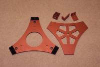
I decided to design my own mirror cell rather than purchase a prebuilt model. There are several makes and models to choose from but I've not found any mid-range mirror cells that I liked. Most are either not substantial enough for imaging or are too expensive. Besides, making my own is more fun.
I will say up front that there is very little in the way of science or proven methodology in this design. I simply tried to use my own sense of weight and rigidity such that the latter would not be compromised. Six spaces were removed in the upper plate to save on weight leaving six spokes that measure 0.5" thick. In theory the spokes will still be plenty rigid while allowing some throughput for air circulation to the base of the primary.
TurboCAD 14 was used to draw each half of the mirror cell. This design assumes 6061 aluminum for the material at a thickness of 0.25". Royce's conical mirrors offer a particular appeal for use in imaging telescopes in that they are cast with a mounting bolt protruding from the base's center. This bolt is intended to be passed through a compatible mirror cell and then locked in place using a washer and nut. Royce's design illiminates the need to epoxy the primary in place. The 8" F/5 mirror uses a standard 3/8-16 bolt so I have placed a mounting hole in the upper plate accordingly.
After a great deal of research and waffling over pointless details I decided on 1/4-28 collimation bolts. This will allow for seven threads to be engaged in the 0.25" cross-section rather than just five threads with say, 1/4-20 for example.
The center hole in the lower plate measures a somewhat arbitrary 3.125" in diameter. This is to allow easy access to the mounting hole for tightening down the locknut as well as allowing air flow to the base of the primary. At some point I may mount an 80mm fan over this hole to aid in faster equalization before beginning an imaging session.
|
|
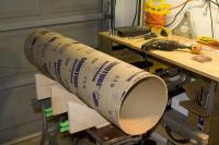
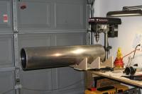
My plans call for a 10"x43" telescope tube. For the time being I have chosen to use aluminum irrigation piping available from a compnay in Nebraska. Hastings Pipe Company has developed a great reputation among the ATM community for the service they are providing to us. This tube was ordered with each end rolled to increase strength. The wall thickness is 0.064". Here it is pictured next to my disassembled Atlas EQ-G for scale.
A long-term goal for this astrograph to have a custom carbon fiber tube. This material provides superior strength and substantail weight savings compared with aluminum. The kicker though is a much lower coefficient of thermal expansion. Focus shift over prolonged imaging sessions is far less of an issue with carbon fiber telescope tubing.
|

The Tube
|
|

The Tube
|
A close-up of one rolled end.
|
|
|
Inside looking out.
|

The Tube
|
|

Making the Mirror Cell
|
I purchased two sections of 12"x12"x0.25" 6061 aluminum flatbar from a local metals supplier. Cosmetically speaking this stuff isn't the best, but true aluminum plating is much more expensive. Each 12" section cost me about $22.
|
|
I took my plates to a local metal fabrication shop to be cut on a water-jet machine. The technician loaded my CAD drawing and away it went. This machine cuts with a 60,000 PSI beam of water about 0.030" thick.
Hammerhead Water-Jet machine: $350,000
Getting your own custom-designed aluminum shapes cut to 0.030" precision - priceless.
|

Making the Mirror Cell
|
|

Making the Mirror Cell
|
Cutting the top plate.
|
|
|
To my dismay the technician was able to cram both halves of the mirror cell onto one 12"x12" section. Now I have a backup plate in case I find that I've royally botched something.
|

Making the Mirror Cell
|
|

Making the Mirror Cell
|
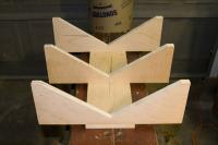
After cutting.
|
|
|
Base plate (left) and mirror-mounting plate (right).
|

Making the Mirror Cell
|
|

Making the Mirror Cell
|
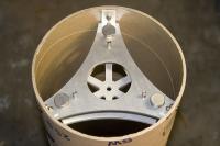
The mirror cell will appear much like this after mounting in the tube.
|
|
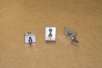
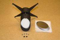
The hardware just arrived. For lack of experience building mirror cells I ordered two different sets of compression springs to feel them out. One set is substantially stiffer than the other, but both are fully capable of lifting the combined weight of the upper plate plus mirror at as little as 0.25" of deflection.
Pictured from left to right (top row first):
1/4-28 stainless knurled thumbscrews, 1.75" shank (collimation bolts)
Stainless compression springs, 1.5" long, 0.375" OD, 17.68 lb/inch
Stainless compression springs, 1.25" long, 0.6" OD, 37.49 lb/inch
1/4-20 stainless knurled thumbscrews, 1.5" shank, (locking bolts)
8-32 stainless socket-head machine screws, 0.75" shank, (mounting bolts)
|

Making the Mirror Cell
|
|

Making the Mirror Cell
|
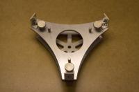
Bottom view.
|
|
|
Top view.
|

Making the Mirror Cell
|
|

Making the Mirror Cell
|
Side view.
|
|
|
.....another view.
|

Making the Mirror Cell
|
|

Making the Mirror Cell
|
Close-up of collimation thumbscrew, locking thumbscrew, and one of the stiffer springs (37.49 lb/inch).
|
|
UPADATE AS OF 12/10/08 - At least four weeks away from my order being filled due to a huge backlog in the Royce shop. I'm not expecting the primary until middle of January.
My order for an 8-inch F/5 Royce conical primary mirror has been placed. Bob Royce chatted with me briefly on the phone and indicated a probable delivery date around the middle of December.
I went with his standard coating which is ~94% reflectivity. Other exotic coatings are available in the 95-98% range but I've learned that these are exremely difficult to remove when it comes time to recoat the glass. In many cases the entire blank has to be refigured which gets expensive.
I'm actually very content with a timeframe of 7-8 weeks. This will give me more than enough time to quit obsessing over the remaining components and get them ordered.
UPDATE (Feb. 20, 2009) - Bob Royce has given me a new prospective delivery of the conical primary mirror sometime in late March.
|
Mirror ordered on October 22, 2008
|
|
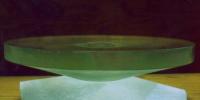
Test assembly using 10
|
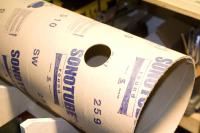
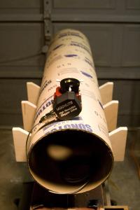
The purpose of this exercise is to ensure that I only drill one set of holes in the Hastings tube. A fellow ATM/astorphotographer gave me the idea to build a dry-run OTA using a cheaper tube material in order to confirm that my camera reaches focus using all of the spacings and dimensions shown in NEWT. This 10" sonotube will be used to build the dry-run OTA. All components will be installed followed by a rough collimation before having first light with a QHY8 CCD camera.
|
|
|
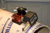
Pictured here is my QHY8 camera attached to the focuser. I chose Moonlight's motorized CR newtonian focuser because it will add several additional technologies to my imaging workflow. Motorized focusing will allow me to stay at the laptop and adjust focus remotely rather than having to lean way over and shake up the mount by manually adjusting focus with my hand. I can also employ various automated focusing utilities, create focusing profiles for multiple cameras and filters, and lastly have the benefit of automated temperature compensation.
|
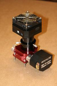
Moonlight CR Newtonian Focuser
|
|
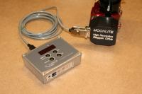
Cercis Controller
|
Several controller options are available with Moonlight's motorized focusers. I chose the Cercis controller because it can control two focuser simultaneously while running seperate temperature profiles for each one. Two temperature probes can be connected as well.
|
|
|
I knocked together this cradle which bolts to my drill press. The cradle provides support and aids in carefully positioning the tube under the bit. The tube can also be clamped or strapped to the cradle.
|
Drilling Cradle
|
|
Focuser Installation (sonotube)
|
The focuser hole was cut using a 2-3/8" hole saw attached to a corded hand-drill. I wasn't able to use the drill press because the hole saw is too tall.
|
|
|
Focuser installed into the sonotube using Moonlight's 10" low-profile adapter.
|
Focuser Installation (sonotube)
|
|
Focuser Installation (sonotube)
|
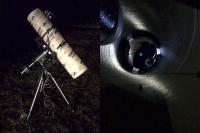
Close-up of focuser installed in the sonotube. This is the Moonlight CR Newtonian focuser with Hi-Res Stepper Motor. I'm using the Cercis controller (not pictured).
|
|
|
Mounting brackets for the mirror cell were fabricated using three 1" sections of aluminum L-channel. I bought these pieces at the local metals supplier for less than a dollar each. One side is longer than the other, measuring 1.5" and 0.75" respectively. The brackets are fastened to both the tube wall and the mirror cell using 10-32 screws. I wanted a small amount of adjustablility with respect to the tube's inner diameter, so I routed slots in the face that abutts the mirror cell (rather than single holes).
|
Installing the Mirror Cell
|
|
Installing the Mirror Cell
|
Mounting brackets attached to the mirror cell.
|
|
|
Mirror cell installed into the sonotube.
|
Installing the Mirror Cell
|
|
Installing the Mirror Cell
|
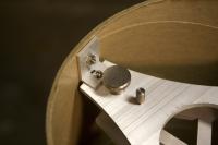
Close-up of mirror cell mounting bracket.
|
|
The spider I ordered from Protostar features a couple of bells and whistles. It comes with an integrated dew heater that runs off a 12V powers source of my choosing. Two of the vanes actually act as positive and negative conductors. Wires can be attached on the outside of the tube and then run to the power source. In my case I'll be using a standard RCA plug so I can connect the integrated secondary dew heater right alongside my other dew heater strips (for guidescope, telrad, etc).
The second enhancement is built-in offset. I simply took the offset amount provided by NEWT and requested that Protostar build it into the spider. This is a standard option they offer and well worth it IMHO.
|
Protostar 4-Vane Spider & ULS Quartz Secondary Mirror
|
|
Focus Test Using Sonotube OTA
|
In late March I mounted the assembled sonotube OTA to shoot some test shots. Again, the purpose of this exercise was to confirm that my camera could reach focus with all components spaced as they are. Unfortunately this trip was a total flop. For some reason there was an electrical outage at the site I have used many times for observing and imaging. After two hours of fumbling around trying to find a solution, Kevin and I called it quits. I made a second attempt the following night. This photo shows the hilarious contraption we rigged up to mount the sonotube to my Atlas EQ-G (it wouldn't fit in the Parallax rings, slightly too wide).
|
|
Not long after the first attempt to test for focus I got it done in my driveway. Driving out to a dark site just for this exercise was overkill.
My QHY8 camera came to focus with room to spare. That'll work!
|
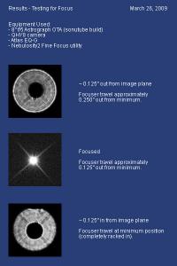
Results Of Successful Focus Test
|
|
Prepping the Hastings Tube
|
This photo shows the Hastings tube mounted to my drilling jig. It looks like it shouldn't be holding itself up there, but there's about 8 lbs worth of weight sitting inside on the end closest to the drill press. I used this jig to drill the mounting holes for the spider and mirror cell.
|
|
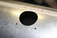
Despite several warnings I received about using a hole saw to drill through a curved metal surface, it worked perfectly for me. I used a handheld corded drill with a 2-3/8" hole saw. The results were perfect. Here's a video of the process that I recorded just to prove that it can be done.
http://www.youtube.com/watch?v=YBslPcwJcjs&feature=channel_page
|
Prepping the Hastings Tube
|
|
Assembled OTA
|
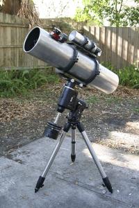
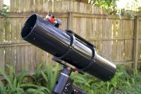
Around the middle of April I installed all components into the Hastings tube and mounted my homemade guidescope. Here the two scopes are mounted to a hypertuned Atlas EQ-G mount in my backyard.
|
|
|
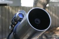
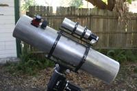
Additional views of the assembled OTA.
|
Assembled OTA
|
|
Assembled OTA
|
Additional views of the assembled OTA.
|
|
|
Additional views of the assembled OTA.
|
Assembled OTA
|
|
First Imaging Session
|
The first serious imaging session took place at the Chiefland Astronomy Village in northern Florida. This event constituted the testing of a prototype that ultimately evolved into a new product line of conical mirror cells available from Optical Supports. The new conical mirror cell that is now in full production can be viewed and purchased at Optical Supports
|
|
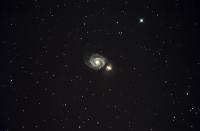
M51 - The Whirlpool Galaxy
3 exposures, 4 minutes each (12 minutes total exposure)
Imaging scope: 8" newtonian astrograph @ f/5
Mount: Orion Atlas EQ-G, "hypertuned", PEC via EQMOD
Autoguiding: 80mm & f/5, Orion Starshoot Autoguider w/ 2.0 second exposures, pulseguiding via PHD/EQASCOM
Focusing: Bahtinov mask and Nebulosity2 Fine Focus
Capture Software: Nebulosity2
Processing: Nebulosity2 and Photoshop CS2
|
Results Of First Imaging Session
|
|
Results Of First Imaging Session
|
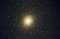
Omega Centauri
13 exposures, 2 minutes each (26 minutes total exposure)
Imaging scope: 8" newtonian astrograph @ f/5
Mount: Orion Atlas EQ-G, "hypertuned", PEC via EQMOD
Autoguiding: 80mm & f/5, Orion Starshoot Autoguider w/ 2.0 second exposures, pulseguiding via PHD/EQASCOM
Focusing: Bahtinov mask and Nebulosity2 Fine Focus
Capture Software: Nebulosity2
Processing: Nebulosity2 and Photoshop CS2
|
|
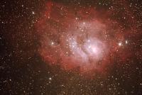
M8 - The Lagoon Nebula
12 exposures, 5 minutes each (60 minutes total exposure)
Imaging scope: 8" newtonian astrograph @ f/5
Mount: Orion Atlas EQ-G, "hypertuned", PEC via EQMOD
Autoguiding: 80mm & f/5, Orion Starshoot Autoguider w/ 2.0 second exposures, pulseguiding via PHD/EQASCOM
Focusing: Bahtinov mask and Nebulosity2 Fine Focus
Capture Software: Nebulosity2
Processing: Nebulosity2 and Photoshop CS2
|
Results Of First Imaging Session
|
|
Analysis - Mount Upgrade
|
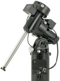
I won't go into a lengthy write-up on this. The short version is that while my results are very promising, I did have several problems during the first imaging session that all point to the need for a mount upgrade.
I'm probably biased, but I feel that this instrument I've built deserves a mounting that can track and guide inside of 5 arcseconds peak-to-peak error. Pictured here is the Astro Physics Mach1GTO. If you know of any philanthropists who are looking to sponsor a budding astrophotographer....please let me know.
|
|
A few finishing touches still need to be wrapped up:
- Anodizing the mirror cell, either black or red (probably red to match the focuser)
- Powder coating the tube either white or black
- Installing the flocked tube liner
It may be awhile before the above list is complete due to the need for upgrading my mount. Hopefully funds will allow it in the not too distant future.
|
Looking Ahead
|
|
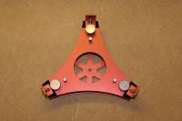
Anodized Mirror Cell
|
After several months of no activity on this project I have finally put on the finishing touches. The plan all along was to anodize the mirror cell red. Sometimes my camera and subsequently RAW settings do weird things with red, but this actually came out extremely close to the Moonlight focuser's shade of red.
|
|
|
Assembled, bottom view.
|
Anodized Mirror Cell
|
|
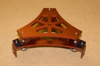
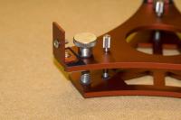
Anodized Mirror Cell
|
Assembled, top view.
|
|
|
Assembled, close-up on hardware and mounting bracket.
|
Anodized Mirror Cell
|
|
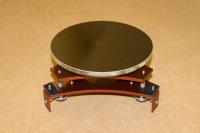
Anodized Mirror Cell
|
Assembled with 8" f/5 Royce conical primary mirror installed. This mirror cell has become the prototype for a new product line of conical mirror cells available from Optical Supports. The new conical mirror cell that is now if full production is available to fit three different apertures manufactured by Bob Royce. More information is available at Optical Supports
|
|
I have spent roughly 11 months building this telescope, and through that time I waffled back and forth on what color to paint the tube. For some reason I have always loved white on telescopes, but for this project I seriously considered black to set off the red anodizing in the focuser and mirror cell. Last week I drove the tube over to my local powder coating shop, still unsure which color I would ask for when I got there. After some conversation with the owner I noticed a sample swatch of gloss black with silver flecking. It was an instantaneous decision. I really could not be happier with how this came out.
|
Powder Coated Tube
|
|
Powder Coated Tube
|
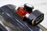
Close-up of the metal flaking on black near the red anodized Moonlite focuser.
|
|
|
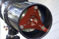
Close-up of the red anodized mirror cell mounted in the tube.
|
Powder Coated Tube
|
|