|
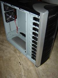
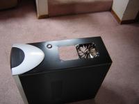
New Cooler Master 810 Case.
|
This is a New Cooler Master 810 case that I am going to modify for water cooling.
|
|
|
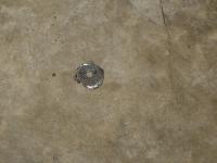
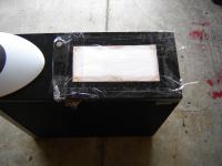
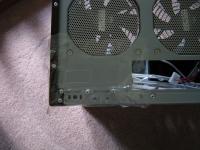
As I needed a filler hole I decided to put in neear where I plan to have the radiator tubing. I also wanted to place it behind the mother board rear edge and in front of the drive cage area.
|
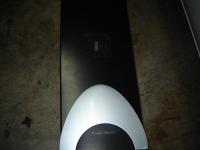
I need a place to fill the cooling loop.
|
|
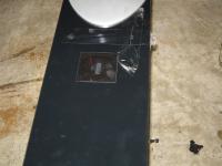
Covering the area in tape to aviod scratchs.
|
I covering the area in tape to aviod scratchs. You never know when a drill bit will walk.
|
|
|
The hole saw wobbled and made a bit of a mess. Good thing the tape was there.
|
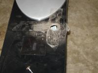
I tried tried use a hole saw and it wobbled.
|
|

I had to use my RBX
|
RBX is like a dremel. Works pretty much the same way.
|
|
|
This is pretty good with an RBX.
|
Not bad.
|
|
Cleaned up the hole a bit
|
I used the RBX and a grinding stone to clean up the hole a bit.
|
|
|
I removed the tape and cleaned up the top a bit.
|
Tape removed
|
|
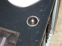
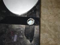
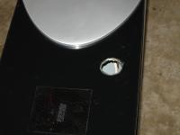
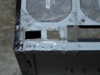
Filler plug installed
|
I installed the filler plug buy unscrewing a plastic ring. I insterted the filler neck in the hole and rethreded the ring. This works well however the hole saw left a mess around the ring. A bit of touch up paint will help a lot.
|
|
|
I rubbed a crayon over the radiator. Thank you Hanna for the crayon. :) This gave me a very good impression of the edges and hole locations.
|
Filler hole fixed and teemplate for radiator setup.
|
|
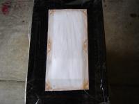
A closer view of the template.
|
I istalled the template with a lot of tape. The fan hole were also dimpled to prevent drill walk.
|
|
|
I drilled the holes first as there was more metal and avoided issues with bending. I then test fit each fan in the holes to be sure they were correct. They were fine.
|
Holes drilled
|
|
Fan area cut out.
|
I used a jigsaw with a 24 tpi blade to cut the metal out. I did not need to cut a hole as I used the 80 mm fan hole in the top. There are some small imperfections. These were cleaned up with the RBX and a grinding stone.
|
|
|
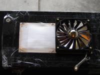
Thisa was a test fit of the cooling fan. I think it looks good.
|
Fan inserted in fan area
|
|
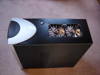
Both fan inserted
|
The fans are now loosly instered in the fan hole.
|
|
|
I used some door sealer on the radiator. This was to seal the fans to the radiator better and provide a 1/4" more room between the fan and radiator. This helps reduce the dead spot where the fan motor is. It helps with the cooling.
|
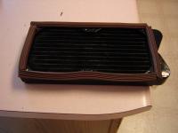
I used some door sealer on the radiator
|
|
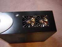
Fans and Radiator intalled
|
There it is the fans installed the radiator installed below and the filler neck installed.
|
|
|
The fans and radiator installed and sealed. The brown sealer is not visible when viewed from the side.
|
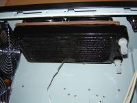
The radiator under the fans and sealed to them.
|
|
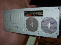
Switch and power location
|
This is the On-Off-On switch and the power location for the pump relay.
|
|
|
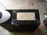
Marked out the power location.
|
Marking out the power location
|
|
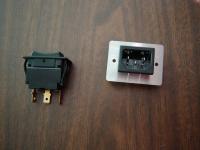
Power switch and the power socket.
|
This is the power socket that came with the pump relay. I decided that the cover would look lame so I removed the hopusing and cut the square hole very tight.
|
|
|
While it looks like I did not line up the marks the switch and socket will fit nicely. Its better to start to small as you can always make the hole bigger. The switch and socket have ribs that grab the edge of the hole to ensure they do not come out.
|
The socket and switch location marked and taped.
|
|
Holes are cut
|
The holes are cut but the switch fit but not long enough and the power was actually to small. However it works beter this way.
|
|
|
I finished the hole and the sizes are right on.
|
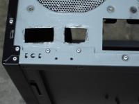
Holes finished
|
|
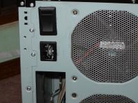
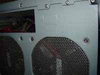
Switch and power connector installed
|
While not the greatest it probably never going to be seen.
The reason I added a switch was si I did not have to move a wire from one side of the realy to the other to bleade the system.
In 1 position the pump will run independent of the computer. In the other it will run only when there is 12V which means only when the system is running.
|
|